100 watt inverter pcb layout
We have 20 QC auditors with three years of experience who use advanced testing equipment such as AOI, BGA X-ray and PCB E-test to ensure that all our products comply with IECQ-HSPM QC 080000, CE, UL and RoHS Certification. All our products comply with international quality standards and our customers come from different markets around the world. For example Virgin Islands,Uzbekistan,Saint Pierre and Miquelon,Malaysia,Timor-Leste,Seychelles etc.
| Model Number | customized PCBA |
| Type | pcba |
| Place of Origin | Guangdong, China |
| Brand Name | none |
| Copper Thickness | 1 oz |
| Supplier Type | OEM |
| Application | Electronics Device |
| Service | One-step Service |
| Layer | 1-38layers |
| Solder mask color | Blue.green.red.black.white.etc |
| Testing Service | 100% |
| Component size | 0201-1138mm |
| Component max height | 30mm |
| Min lead pitch | 0.4mm |
| Min BGA ball pitch | 0.4mm |
| Max PCB size | 518x422mm |
| Packaging Details | Vacuum package for bare PCB and ESD package for PCBA Printed Circuit Board Factory FPC Board PCBA Companies PCBA Assembly |
| Supply Ability | 59980 Piece/Pieces per Week |
| Quantity (pieces) | > 844 |
| Lead time (days) | 11 |
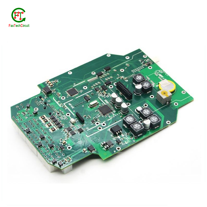
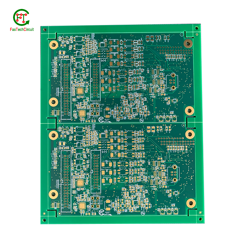
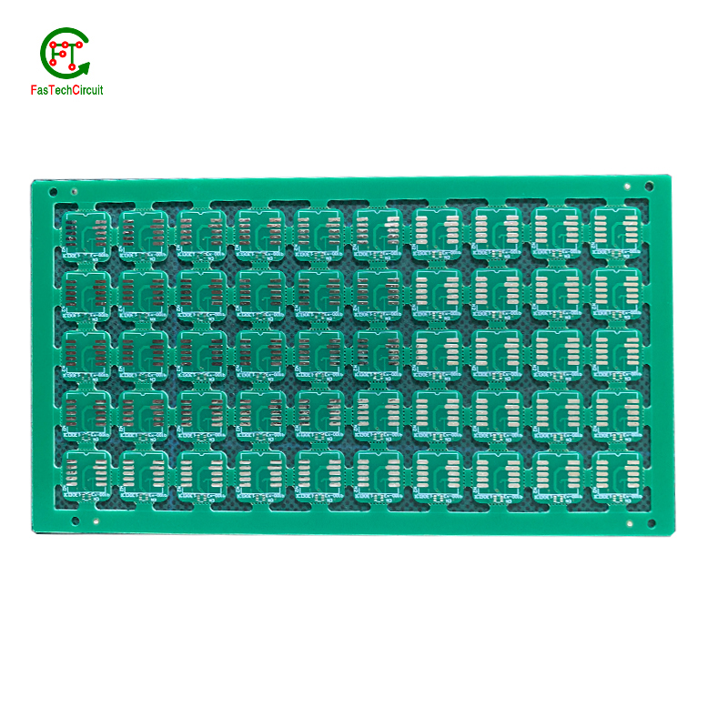
100 watt inverter pcb layout bearings FAQs Guide Welcome to our state-of-the-art PCB (Printed Circuit Board) products. We are proud to offer a comprehensive range of high-quality and versatile PCB solutions to meet the constantly evolving needs of the modern electronics industry.Our PCBs are expertly designed and manufactured using the latest technology and advanced techniques, ensuring reliability, durability, and exceptional performance for a wide range of applications. We understand the importance of precision and attention to detail in the production of PCBs and we are committed to meeting stringent quality standards.
2.What is the minimum size of a through-hole component that can be used on a 100 watt inverter pcb layout?
3.How are 100 watt inverter pcb layout used in medical devices?
4.How are 100 watt inverter pcb layouts protected from environmental factors?
5.What are the main components of a 100 watt inverter pcb layout?
6.What is the purpose of a 100 watt inverter pcb layout?
7.Can a 100 watt inverter pcb layout be used for both power and signal transmission?
8.How is a 100 watt inverter pcb layout tested for functionality?
9.How are components attached to a 100 watt inverter pcb layout?
10.Can 100 watt inverter pcb layouts be customized?
11.What are the most common uses for 100 watt inverter pcb layout?
12.What techniques are used for reducing electromagnetic interference (EMI) on a 100 watt inverter pcb layout?
13.What are some common problems that can occur with 100 watt inverter pcb layout?
14.What is the power rating for a 100 watt inverter pcb layout?
1.What software is used for 100 watt inverter pcb layout design?
Our 100 watt inverter pcb layout products have competitive and differentiated advantages, and actively promote digital transformation and innovation.
Some popular software used for PCB design include:
1. Altium Designer
2. Eagle PCB
3. KiCad
4. OrCAD
5. PADS
6. Proteus
7. DipTrace
8. EasyEDA
9. CircuitMaker
10. DesignSpark PCB
2.What is the minimum size of a through-hole component that can be used on a 100 watt inverter pcb layout?
We continue to invest in research and development and continue to launch innovative products.
The minimum size of a through-hole component that can be used on a PCB depends on the capabilities of the PCB manufacturer and the design requirements of the circuit. Generally, the minimum size for a through-hole component is around 0.2mm in diameter, but some manufacturers may be able to produce smaller sizes. It is important to consult with the manufacturer and consider the design requirements to determine the appropriate size for a through-hole component on a PCB.
3.How are 100 watt inverter pcb layout used in medical devices?
Printed Circuit Boards (PCBs) are essential components used in a wide range of medical devices, playing a crucial role in both diagnostic and treatment equipment. These devices require reliable and precise circuitry to accurately collect and process data, deliver therapies, and regulate medical procedures. PCBs are used in equipment such as MRI machines, pacemakers, defibrillators, and monitors, where their small size and high density make them ideal for compact and portable designs. In addition, PCBs are also used in medical implants, enabling a safe and secure connection between the device and the body. With their advanced technology, PCBs continue to be an integral part of the medical industry, ensuring the effectiveness and success of various medical procedures and treatments.
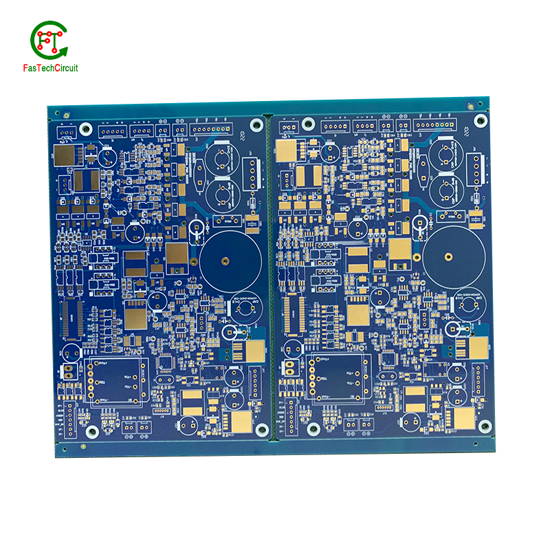
4.How are 100 watt inverter pcb layouts protected from environmental factors?
We have established long-term and stable partnerships with our suppliers, so we have great advantages in price and cost and quality assurance.
PCBs, or printed circuit boards, are protected from environmental factors through the use of various techniques and materials. One method is to coat the PCB with a layer of conformal coating, which is a thin layer of protective material that covers the components and circuitry on the board. This coating can protect the PCB from moisture, dust, and other contaminants that could cause damage.
In addition to conformal coating, PCBs can also be protected through designing the layout of the board in a way that minimizes exposure to environmental factors. This includes placing sensitive components in areas that are less susceptible to moisture or temperature changes, as well as using specialized materials that are resistant to the effects of heat, humidity, and other environmental conditions.
5.What are the main components of a 100 watt inverter pcb layout?
We continuously upgrade our skills and knowledge to adapt to changing 100 watt inverter pcb layout market needs.
A typical PCB consists of several vital components, including a substrate material, copper traces, solder mask, silk screen, and plated through-holes. The substrate material acts as the base and provides mechanical support for the board. Copper traces, usually made of thin lines of copper foil, serve as the conductive paths for transmitting electrical signals. The solder mask, applied as a protective layer, prevents accidental short circuits and corrosion. Silk screen, a layer of ink-based labeling, aids in component identification. Lastly, plated through-holes enable electrical connection between different layers of the PCB board. These components work together to form a fully functioning PCB.
6.What is the purpose of a 100 watt inverter pcb layout?
We pay attention to the transformation of intellectual property protection and innovation achievements. Your OEM or ODM order design we have a complete confidentiality system.
A PCB (Printed Circuit Board) is a flat board made of non-conductive material, such as fiberglass, with conductive pathways etched or printed onto it. The main purpose of a PCB is to provide a platform for electronic components to be mounted and connected together to form a functioning electronic circuit. It serves as a physical support for the components and provides a means for them to communicate with each other through the conductive pathways. PCBs are used in a wide range of electronic devices, from simple household appliances to complex computer systems, and are essential for the proper functioning and reliability of these devices. They also allow for easier and more efficient production of electronic devices, as the components can be mounted and connected in a standardized and automated manner.
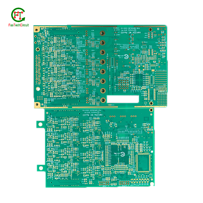
7.Can a 100 watt inverter pcb layout be used for both power and signal transmission?
Yes, a PCB (printed circuit board) can be used for both power and signal transmission. This is commonly seen in electronic devices such as computers, smartphones, and other electronic devices. The PCB acts as a platform for connecting various components and circuits, including power sources and signal pathways. The power and signal traces on the PCB are designed to handle different levels of current and voltage to ensure efficient transmission and prevent interference between the two. However, it is important to properly design and layout the PCB to ensure proper separation and isolation of power and signal traces to avoid any potential issues.
8.How is a 100 watt inverter pcb layout tested for functionality?
A PCB, or Printed Circuit Board, is tested for functionality to ensure that all components and connections on the board are working correctly. This is important in order to detect any potential manufacturing or design defects that could compromise the board's performance. To test a PCB, a range of diagnostic tools and techniques are used including visual inspection, automated testing software, and specialized equipment such as oscilloscopes and multimeters. Experienced technicians also use their knowledge and expertise to troubleshoot and identify any issues with the board. Through this rigorous testing process, any faults or failures are identified and resolved before the PCB is released for production, ensuring that it meets the desired functionality and performance standards.
9.How are components attached to a 100 watt inverter pcb layout?
We adhere to the principle of integrity and transparency, and establish long -term relationships with partners, and we attach great importance to this detail.
eads or pins of the component and melting solder onto them, whicComponents are attached to a PCB (printed circuit board) through a process called soldering. This involves heating the metal lh then solidifies and creates a strong electrical and mechanical connection between the component and the PCB. There are two main methods of soldering components onto a PCB:
1. Through-hole soldering: This method involves inserting the leads or pins of the component through pre-drilled holes on the PCB and soldering them on the opposite side of the board. This method is commonly used for larger components such as resistors, capacitors, and integrated circuits.
2. Surface mount soldering: This method involves soldering the component directly onto the surface of the PCB, without the need for pre-drilled holes. This is done using specialized equipment such as a soldering iron or a reflow oven. Surface mount components are smaller in size and are commonly used for more complex and compact electronic devices.
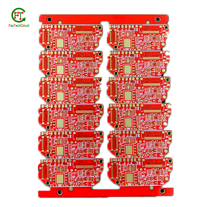
10.Can 100 watt inverter pcb layouts be customized?
We should enjoy a good reputation in the industry, and we can increase the added value of the products of cooperative customers through technological innovation.
Yes, PCBs (printed circuit boards) can be customized to meet specific design requirements. This can include changes to the size, shape, number of layers, and placement of components on the board. Customization can also involve the use of specialized materials, finishes, and manufacturing processes to meet specific performance or environmental requirements. PCB manufacturers often offer design services to help customers create custom PCBs that meet their unique needs.
11.What are the most common uses for 100 watt inverter pcb layout?
We enjoy high authority and influence in the industry and continue to innovate products and service models.
Printed circuit boards, or PCBs, are widely used in electronic devices and equipment. They are used in everything from smartphones and computers to household appliances and automotive systems. PCBs are essential components for connecting electrical and electronic components together, providing a robust and reliable platform for digital and analog signals to pass through. Common uses for PCBs include controlling and powering electronic devices, storing and processing data, and providing a means of communication between components. They are also used in various industrial and commercial applications, such as automation and control systems, medical equipment, and aerospace technology. PCBs offer a cost-effective and efficient solution for creating complex electronic circuits, making them a crucial component in modern technology.
12.What techniques are used for reducing electromagnetic interference (EMI) on a 100 watt inverter pcb layout?
Electromagnetic interference (EMI) is a disturbance caused by electromagnetic radiation that can disrupt the proper functioning of electronic devices. To reduce EMI on a PCB, a number of techniques can be employed. One common technique is to use a ground plane, which acts as a shield to block electromagnetic waves from interfering with the circuit. Another approach is to use proper placement and routing of components and traces to minimize the length of signal paths and reduce the chances of signal crossover. Additionally, using components like capacitors and ferrite beads can help to filter out high-frequency noise. Careful consideration and design of the PCB layout is also crucial in reducing EMI, as the placement, size, and orientation of components can impact electromagnetic emissions. By employing these techniques, EMI on a PCB can be effectively reduced, leading to improved performance and reliability of electronic devices.

13.What are some common problems that can occur with 100 watt inverter pcb layout?
Our 100 watt inverter pcb layout products undergo strict quality control to ensure customer satisfaction.
PCB (printed circuit boards) are an integral part of electronic devices, serving as the foundation for electrical connections and components. However, like any other technology, there are certain issues that may arise with PCB. One common problem is damage to the board due to excessive heat, as electronic components generate heat and if the PCB is not properly designed or ventilated, it can lead to malfunctions or even permanent damage. Another issue is poor soldering, which can result in weak connections or no connection at all. This can be caused by inadequate equipment or inexperience in the assembly process. Additionally, PCB can also suffer from corrosion over time, especially in high humidity environments, affecting its performance and reliability. It is important to address these problems early on to prevent further damage and ensure the functionality of electronic devices. Regular maintenance, proper design and assembly techniques, and use of quality materials can help prevent these common issues with PCB.
14.What is the power rating for a 100 watt inverter pcb layout?
We maintain a certain amount of R&D investment every year and continuously improve operational efficiency to provide better services to our cooperative customers.
The power rating for a PCB (printed circuit board) can vary greatly depending on its size, design, and intended use. Generally, the power rating for a PCB is determined by the maximum amount of current it can safely handle without overheating or causing damage. This can range from a few milliamps for small, low-power circuits to several amps for larger, high-power circuits. It is important to consult the manufacturer's specifications or consult with an engineer to determine the specific power rating for a particular PCB.
RELATED PRODUCTS & SERVICE
pcb board manufacturing How To Contact US
PCB from 1 to 30 layers, HDI, Heavy Copper, Rigid-flex board with "pcb board manufacturing One-Stop" service.

