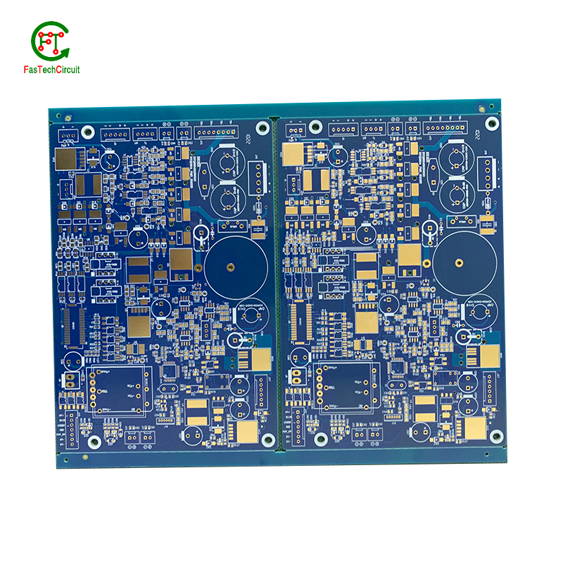
ada1713 pcb layout
FasTechCircuit has established market development, product development, production engineering, process control, quality assurance, material control, and after-sales service management systems. Our products are widely used in various fields such as communications, industrial control, computer applications, aerospace, military, medical, and testing instruments. We can provide one-stop OEM service with price advantage and fast delivery! Our products h
| Base Material | FR-4/CEM-1/CEM-3/Polyimild/PTFE/Rogers |
| Board Thickness | 0.2-6mm |
| Model Number | Custom PCB & PCB Assembly |
| Type | Aluminum PCB |
| Brand Name | FC |
| Copper Thickness | 0.2-2mil(7-45um) |
| Min. Hole Size | 0.1mm(4mil)for HDI / 0.15mm(6mil) |
| Min. Line Width | 0.075mm/0.075mm(3mil/3mil) |
| Min. Line Spacing | 0.003'' |
| Surface Finishing | HASL/OSP/Ag/ENIG/ENEPIG/Immersion silver/Tin |
| Board Size | Custom |
| Model Number | Customized |
| Base Material | FR4 Aluminum CEM-1 94V0 |
| Surface Finishing | HASLENIG OSP |
| Number of layer | 1-17layer |
| Other service | Components purchasing and assem |
| ly Solder mask | White Black Green Blue,Red,etc. |
| Dsign service | Available |
| Testing | Function testing |
| Certificate | RoHS, ISO/TS16949, ISO9001 |
| Name | High Quality led light aluminum pcb printed circuit board |
| Packaging Details | Vaccum package and standard carton outside High Quality led light aluminum pcb printed circuit board |
| Supply Ability | 47634 Square Meter/Square Meters per Month |
| Quantity (pieces) | > 11825 |
| Lead time (days) | 8 |
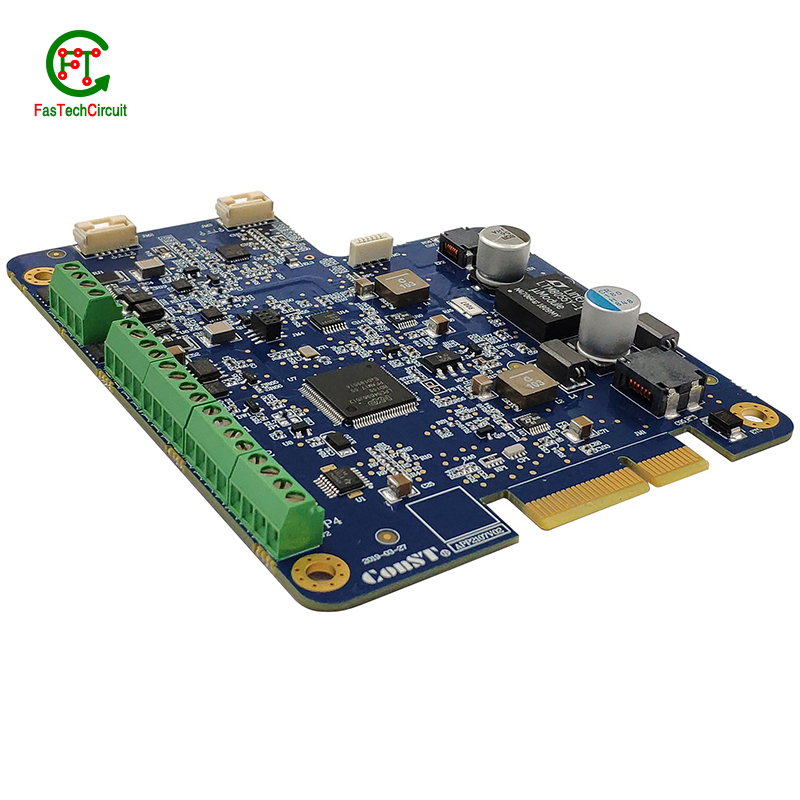
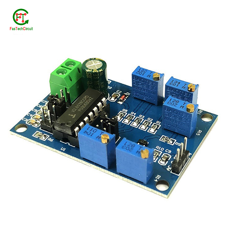
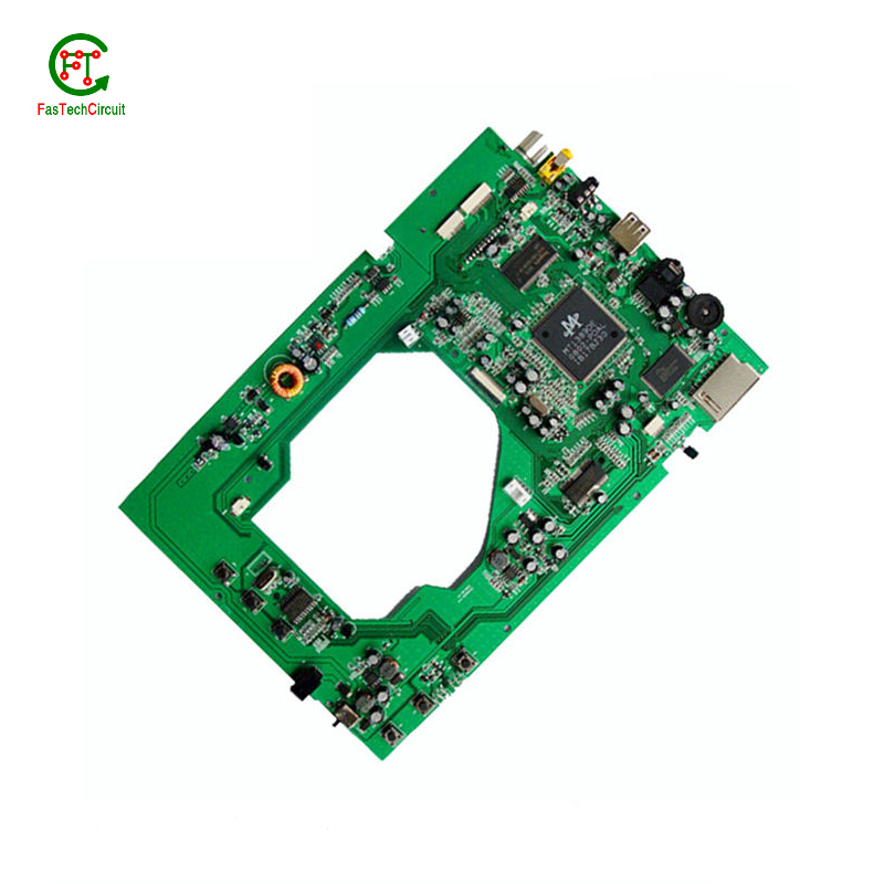
ada1713 pcb layout bearings FAQs Guide Welcome to our state-of-the-art PCB (Printed Circuit Board) products. We are proud to offer a comprehensive range of high-quality and versatile PCB solutions to meet the constantly evolving needs of the modern electronics industry.Our PCBs are expertly designed and manufactured using the latest technology and advanced techniques, ensuring reliability, durability, and exceptional performance for a wide range of applications. We understand the importance of precision and attention to detail in the production of PCBs and we are committed to meeting stringent quality standards.
2.What type of solder is used for ada1713 pcb layout assembly?
3.What is embedded ada1713 pcb layout technology?
4.What is the difference between a diode and a capacitor?
5.Can ada1713 pcb layouts be customized?
6.How are components selected for a ada1713 pcb layout design?
7.What materials are used to make a ada1713 pcb layout?
8.What is the difference between single-sided, double-sided, and multi-layer ada1713 pcb layout?
9.What software is used for ada1713 pcb layout design?
10.How are high-frequency signals handled on a ada1713 pcb layout?
11.What type of material is used for the silkscreen on a ada1713 pcb layout?
12.What are some common ada1713 pcb layout layout guidelines?
13.Can ada1713 pcb layouts be used in high voltage applications?
14.What is the minimum thickness of a ada1713 pcb layout?
15.Can ada1713 pcb layouts be used for high-temperature applications?
16.How are thermal considerations taken into account during ada1713 pcb layout design?
17.What is a ada1713 pcb layout?
1.What techniques are used for reducing electromagnetic interference (EMI) on a ada1713 pcb layout?
Electromagnetic interference (EMI) is a disturbance caused by electromagnetic radiation that can disrupt the proper functioning of electronic devices. To reduce EMI on a PCB, a number of techniques can be employed. One common technique is to use a ground plane, which acts as a shield to block electromagnetic waves from interfering with the circuit. Another approach is to use proper placement and routing of components and traces to minimize the length of signal paths and reduce the chances of signal crossover. Additionally, using components like capacitors and ferrite beads can help to filter out high-frequency noise. Careful consideration and design of the PCB layout is also crucial in reducing EMI, as the placement, size, and orientation of components can impact electromagnetic emissions. By employing these techniques, EMI on a PCB can be effectively reduced, leading to improved performance and reliability of electronic devices.
2.What type of solder is used for ada1713 pcb layout assembly?
The most commonly used solder for PCB assembly is a lead-free solder, specifically a tin-silver-copper (SnAgCu) alloy. This type of solder is preferred due to its high melting point, good wetting properties, and compatibility with surface mount technology (SMT) components. Other types of solder that may be used include tin-lead (SnPb) solder and lead-free alternatives such as tin-copper (SnCu) and tin-bismuth (SnBi) alloys. The specific type of solder used may vary depending on the application and industry standards.
3.What is embedded ada1713 pcb layout technology?
Our products & services cover a wide range of areas and meet the needs of different fields.
Embedded PCB technology refers to the integration of electronic components directly onto a printed circuit board (PCB) during the manufacturing process. This allows for a more compact and efficient design, as well as improved reliability and performance. The components are embedded within the layers of the PCB, rather than being mounted on the surface, resulting in a more streamlined and durable product. This technology is commonly used in applications such as smartphones, tablets, and other portable electronic devices.
4.What is the difference between a diode and a capacitor?
We have a first -class management team, and we pay attention to teamwork to achieve common goals.
A diode is an electronic component that allows current to flow in only one direction. It has two terminals, an anode and a cathode, and works by allowing current to flow from the anode to the cathode, but not in the reverse direction.
A capacitor, on the other hand, is an electronic component that stores electrical energy in an electric field. It has two conductive plates separated by an insulating material, and when a voltage is applied, one plate accumulates a positive charge and the other accumulates a negative charge. This allows the capacitor to store energy and release it when needed.
5.Can ada1713 pcb layouts be customized?
We should enjoy a good reputation in the industry, and we can increase the added value of the products of cooperative customers through technological innovation.
Yes, PCBs (printed circuit boards) can be customized to meet specific design requirements. This can include changes to the size, shape, number of layers, and placement of components on the board. Customization can also involve the use of specialized materials, finishes, and manufacturing processes to meet specific performance or environmental requirements. PCB manufacturers often offer design services to help customers create custom PCBs that meet their unique needs.
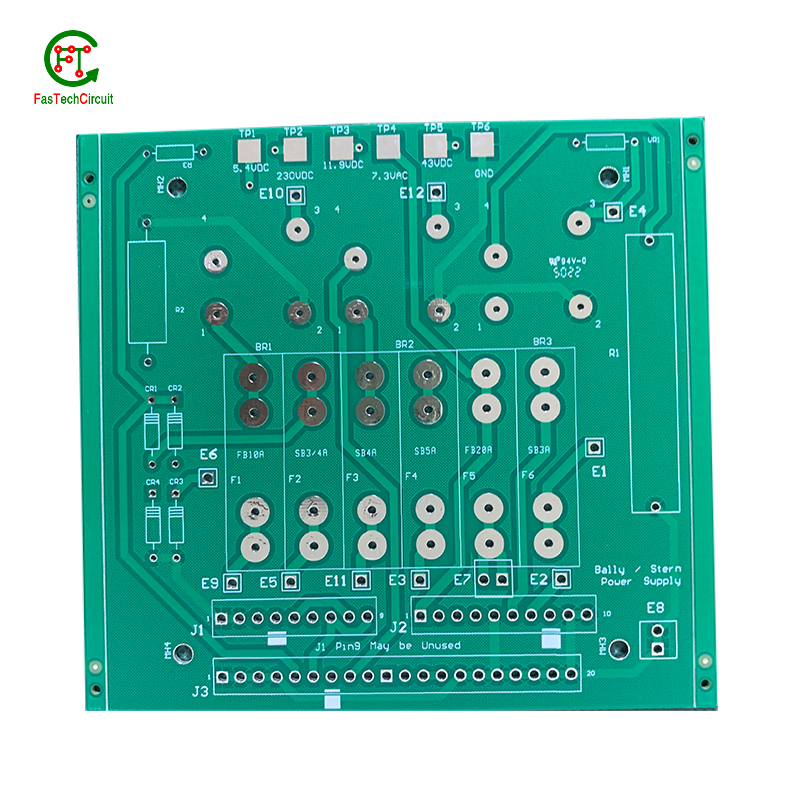
6.How are components selected for a ada1713 pcb layout design?
We pay attention to employee development and benefits, and provide a good working environment in order to improve the efficiency of employees and improve the quality management of ada1713 pcb layout products.
A power rating for a PCB, or Printed Circuit Board, is a measure of the maximum amount of power the board is able to safely handle. This rating takes into account the overall design and materials used in the creation of the PCB, as well as the environment in which it will be used. It is an important consideration in electronics and circuit design as exceeding the power rating can lead to overheating and potential damage to the board and connected components. Properly understanding and adhering to the power rating of a PCB is crucial for ensuring safe and efficient operation of electronic devices.
7.What materials are used to make a ada1713 pcb layout?
We have advanced production equipment and technology to meet the needs of customers, and can provide customers with high quality, low priced ada1713 pcb layout products.
A PCB, or printed circuit board, is typically made of a non-conductive material such as fiberglass or composite epoxy resin. This material acts as a base for a thin layer of copper foil, which is then etched to create the desired circuit pattern. Other common materials used in the production of PCBs include solder mask, a polymer layer used to insulate and protect the copper traces, and silkscreen, which is used to label and identify the different components on the PCB. In addition, various electronic components such as resistors, capacitors, and diodes are also mounted onto the PCB to form a functional electronic circuit. Other potential materials used in the production of PCBs include metal core, ceramics, and conductive ink, depending on the specific design and requirements of the circuit.
8.What is the difference between single-sided, double-sided, and multi-layer ada1713 pcb layout?
We have established a good reputation and reliable partnerships within the ada1713 pcb layout industry.
Single-sided PCB (Printed Circuit Board) is a type of PCB that has components and traces on only one side of the board. The other side is usually used for soldering and mounting the board onto a larger circuit.
Double-sided PCB is a type of PCB that has components and traces on both sides of the board. The traces on both sides are connected through vias, which are small holes drilled through the board and plated with metal to create an electrical connection.
Multi-layer PCB is a type of PCB that has multiple layers of conductive material and insulating material sandwiched together. The layers are connected through vias, allowing for more complex and compact circuit designs. Multi-layer PCBs are used in more advanced and high-performance electronic devices.
9.What software is used for ada1713 pcb layout design?
Our ada1713 pcb layout products have competitive and differentiated advantages, and actively promote digital transformation and innovation.
Some popular software used for PCB design include:
1. Altium Designer
2. Eagle PCB
3. KiCad
4. OrCAD
5. PADS
6. Proteus
7. DipTrace
8. EasyEDA
9. CircuitMaker
10. DesignSpark PCB
10.How are high-frequency signals handled on a ada1713 pcb layout?
High-frequency signals are typically handled with great care and precision on a PCB to ensure optimal performance. This involves using high-quality materials, such as high-speed laminates and low-loss dielectrics, to minimize signal loss and interference. Additionally, designers must carefully consider the trace routing and placement of components on the PCB to minimize signal reflections and keep the signal path as short and direct as possible. Specialized techniques, like controlled impedance and shielding, may also be used to further improve signal integrity.
11.What type of material is used for the silkscreen on a ada1713 pcb layout?
We have a wide range of ada1713 pcb layout customer groups and establishes long -term cooperative relationships with partners. The countries we provide services include .
The material used for the silkscreen on a PCB is typically a white or black ink made of epoxy or acrylic. It is applied using a screen printing process and is cured at high temperatures to ensure durability and resistance to chemicals and solvents.
12.What are some common ada1713 pcb layout layout guidelines?
We should have a stable supply chain and logistics capabilities, and provide customers with high -quality, low -priced ada1713 pcb layout products.
Thermal considerations play a crucial role in the design of printed circuit boards (PCBs). The concept of heat management is critical as excessive heat can lead to reduced performance and potential damage to the electronic components on the board. This is why thermal considerations are carefully taken into account during PCB design. Designers must carefully consider factors such as the size, placement, and orientation of components on the board to ensure efficient heat dissipation. They also need to factor in the type and thickness of the board material, as well as incorporate proper ventilation and heat sinks to prevent overheating. By carefully considering these thermal aspects during the design process, the resulting PCBs can perform optimally and have a longer lifespan.
13.Can ada1713 pcb layouts be used in high voltage applications?
We have advantages in marketing and channel expansion. Suppliers have established good cooperative relations, continuously improved workflows, improved efficiency and productivity, and provided customers with high -quality products and services.
Yes, PCBs (printed circuit boards) can be used in high voltage applications. However, the design and construction of the PCB must be carefully considered to ensure it can withstand the high voltage without causing damage or malfunction. This may include using specialized materials, increasing the spacing between components, and implementing proper insulation and grounding techniques. It is important to consult with a qualified engineer or designer when using PCBs in high voltage applications to ensure safety and reliability.
14.What is the minimum thickness of a ada1713 pcb layout?
We are committed to providing personalized solutions and established long -term strategic cooperative relationships with customers.
The minimum thickness of a PCB (printed circuit board) can vary depending on the materials and manufacturing processes used. However, the standard minimum thickness for a single-sided PCB is 0.6mm (0.024 inches) and for a double-sided PCB it is 0.8mm (0.032 inches). Thinner PCBs can be made, but they may be more fragile and have limitations on the components and circuitry that can be used.
15.Can ada1713 pcb layouts be used for high-temperature applications?
Yes, PCBs (printed circuit boards) can be used for high-temperature applications. However, the materials and design of the PCB must be carefully chosen to ensure that it can withstand the high temperatures without degrading or malfunctioning.
Some factors to consider when using PCBs for high-temperature applications include the type of substrate material, the type of solder used, and the thickness of the copper traces. High-temperature substrates such as ceramic or polyimide can withstand temperatures up to 300°C, while standard FR4 substrates are only suitable for temperatures up to 130°C.
Specialized solder materials, such as high-temperature lead-free solders, may also be necessary to ensure the reliability of the PCB at high temperatures. Additionally, thicker copper traces can help dissipate heat more effectively and prevent damage to the PCB.

16.How are thermal considerations taken into account during ada1713 pcb layout design?
As one of the top ada1713 pcb layout manufacturers in China, we take this very seriously.
Thermal considerations are crucial in the design of printed circuit boards (PCB), as excessive heat can greatly affect the performance and lifespan of electronic components. PCB design engineers must carefully consider thermal management strategies, such as proper placement of heat-generating components, effective heat dissipation techniques, and optimal selection of materials. Thermal simulations and analysis are also commonly used to evaluate and optimize the PCB design to ensure that the temperature of the PCB and its components are within safe limits. By taking into account these thermal considerations, the finished PCB can perform reliably and efficiently, ensuring the overall quality and function of electronic devices.
17.What is a ada1713 pcb layout?
We pay attention to user experience and product quality, and provide the best product quality and lowest production cost for cooperative customers.
A PCB (Printed Circuit Board) is a flat board made of non-conductive material, such as fiberglass, with conductive pathways etched or printed onto it. It is used to mechanically support and electrically connect electronic components using conductive tracks, pads, and other features etched from copper sheets laminated onto a non-conductive substrate. PCBs are commonly used in electronic devices such as computers, smartphones, and televisions to provide a platform for the components to be mounted and connected together. They are also used in a variety of other applications, including automotive, aerospace, and medical devices.
RELATED PRODUCTS & SERVICE
pcb board manufacturing How To Contact US
PCB from 1 to 30 layers, HDI, Heavy Copper, Rigid-flex board with "pcb board manufacturing One-Stop" service.

