60 pcb plate
We have 20 QC auditors with three years of experience who use advanced testing equipment such as AOI, BGA X-ray and PCB E-test to ensure that all our products comply with IECQ-HSPM QC 080000, CE, UL and RoHS Certification. All our products comply with international quality standards and our customers come from different markets around the world. For example Colombia,Netherlands,Kazakhstan,Antigua and Barbuda etc.
| Model Number | customized PCBA |
| Type | pcba |
| Place of Origin | Guangdong, China |
| Brand Name | none |
| Copper Thickness | 1 oz |
| Supplier Type | OEM |
| Application | Electronics Device |
| Service | One-step Service |
| Layer | 1-44layers |
| Solder mask color | Blue.green.red.black.white.etc |
| Testing Service | 100% |
| Component size | 0201-1162mm |
| Component max height | 25mm |
| Min lead pitch | 0.2mm |
| Min BGA ball pitch | 0.5mm |
| Max PCB size | 421x390mm |
| Packaging Details | Vacuum package for bare PCB and ESD package for PCBA Printed Circuit Board Factory FPC Board PCBA Companies PCBA Assembly |
| Supply Ability | 40357 Piece/Pieces per Week |
| Quantity (pieces) | > 843 |
| Lead time (days) | 5 |
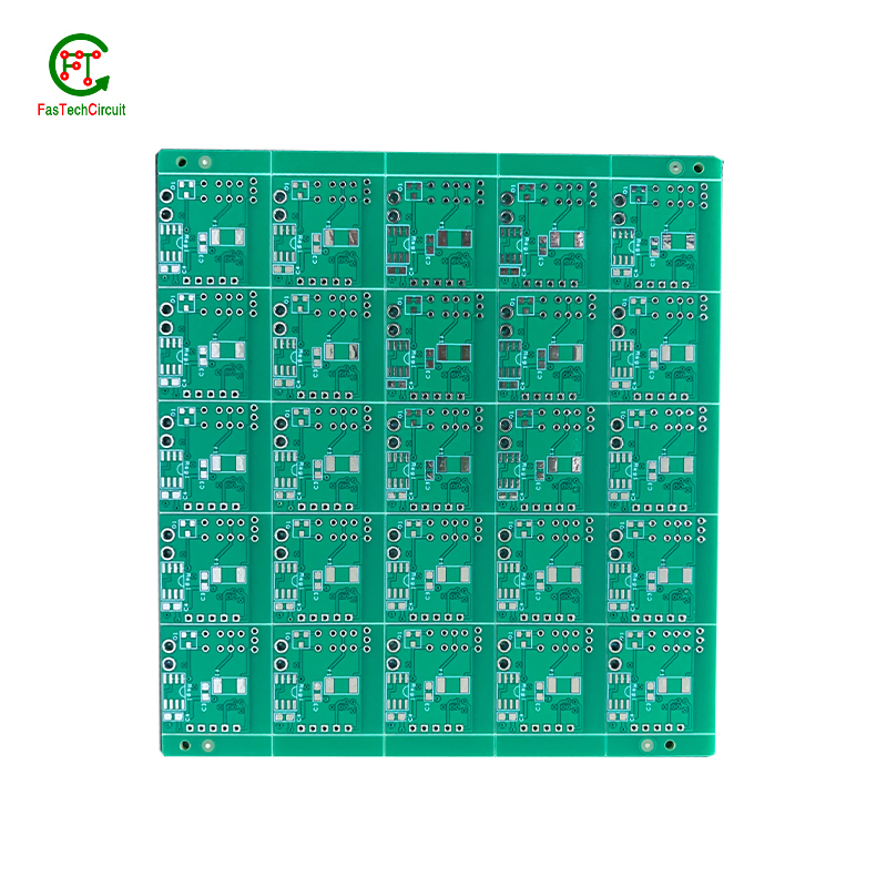
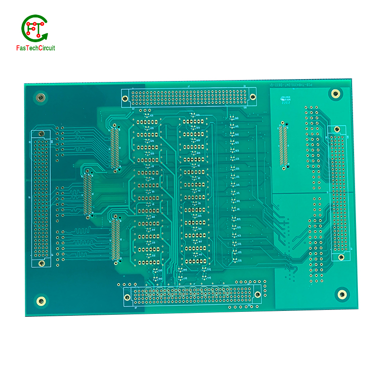
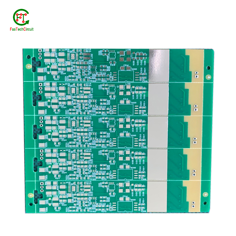
60 pcb plate bearings FAQs Guide Welcome to our state-of-the-art PCB (Printed Circuit Board) products. We are proud to offer a comprehensive range of high-quality and versatile PCB solutions to meet the constantly evolving needs of the modern electronics industry.Our PCBs are expertly designed and manufactured using the latest technology and advanced techniques, ensuring reliability, durability, and exceptional performance for a wide range of applications. We understand the importance of precision and attention to detail in the production of PCBs and we are committed to meeting stringent quality standards.
2.What is the power rating for a 60 pcb plate?
3.Can a 60 pcb plate be repaired if damaged?
4.What is the difference between a copper pour and a trace on a 60 pcb plate?
5.Can 60 pcb plates be used in high voltage applications?
6.What are the main components of a 60 pcb plate?
7.How are components attached to a 60 pcb plate?
8.How are 60 pcb plates designed?
9.How are holes drilled into a 60 pcb plate?
10.How are 60 pcb plates tested for quality control?
11.What is the role of a data sheet in 60 pcb plate design?
12.What is the minimum size of a through-hole component that can be used on a 60 pcb plate?
13.How are high-speed/high-frequency 60 pcb plate tested and validated?
14.What is the difference between an analog and a digital signal on a 60 pcb plate?
15.How are components selected for a 60 pcb plate design?
16.What is the maximum size of a 60 pcb plate?
1.What is noise coupling and how can it be prevented on a 60 pcb plate?
We are a professional 60 pcb plate company dedicated to providing high quality products and services.
Signal traces on a PCB (printed circuit board) are routes created to connect electronic components and allow for the transfer of electrical signals. These traces are typically made from copper and are carefully routed and designed to ensure efficient and reliable signal flow. The routing of signal traces is a critical aspect of PCB design and involves determining the best paths for the traces to minimize interference and optimize signal integrity. This is achieved through techniques such as controlled impedance routing, differential pair routing, and length-matching. Properly routing signal traces on a PCB is crucial for ensuring a functional and high-performance electronic circuit.
2.What is the power rating for a 60 pcb plate?
We maintain a certain amount of R&D investment every year and continuously improve operational efficiency to provide better services to our cooperative customers.
The power rating for a PCB (printed circuit board) can vary greatly depending on its size, design, and intended use. Generally, the power rating for a PCB is determined by the maximum amount of current it can safely handle without overheating or causing damage. This can range from a few milliamps for small, low-power circuits to several amps for larger, high-power circuits. It is important to consult the manufacturer's specifications or consult with an engineer to determine the specific power rating for a particular PCB.
3.Can a 60 pcb plate be repaired if damaged?
We focus on teamwork and communication to achieve common goals, We attach great importance to this detail.
Yes, a PCB (printed circuit board) can be repaired if it is damaged. The extent of the damage and the complexity of the circuit will determine the difficulty and feasibility of the repair. Some common methods for repairing a damaged PCB include:
1. Soldering: If the damage is limited to a few components or traces, they can be replaced or repaired by soldering new components or wires onto the board.
2. Trace repair: If a trace (conductive pathway) on the PCB is damaged or broken, it can be repaired by using a conductive ink or wire to bridge the gap.
3. Component replacement: If a specific component on the PCB is damaged, it can be replaced with a new one. This requires identifying the damaged component and sourcing a replacement.
4. PCB rework: In some cases, the entire PCB may need to be reworked, which involves removing and replacing multiple components and traces.
4.What is the difference between a copper pour and a trace on a 60 pcb plate?
We adhere to the principle of quality first and have a complete production quality management system and quality inspection process.
A copper pour and a trace are two common electronic components that are found on a printed circuit board (PCB). A copper pour is a large area of copper that is used to connect multiple components or ground signals together on a PCB. This creates a solid and low resistance pathway for signals to flow. On the other hand, a trace is a thin line of copper used to connect individual components on a PCB. It carries a specific signal from one component to another. Unlike a copper pour, a trace can be designed to carry a specific current and have a specific width to meet the requirements of the circuit.
5.Can 60 pcb plates be used in high voltage applications?
We have advantages in marketing and channel expansion. Suppliers have established good cooperative relations, continuously improved workflows, improved efficiency and productivity, and provided customers with high -quality products and services.
Yes, PCBs (printed circuit boards) can be used in high voltage applications. However, the design and construction of the PCB must be carefully considered to ensure it can withstand the high voltage without causing damage or malfunction. This may include using specialized materials, increasing the spacing between components, and implementing proper insulation and grounding techniques. It is important to consult with a qualified engineer or designer when using PCBs in high voltage applications to ensure safety and reliability.
6.What are the main components of a 60 pcb plate?
We continuously upgrade our skills and knowledge to adapt to changing 60 pcb plate market needs.
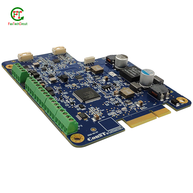
A typical PCB consists of several vital components, including a substrate material, copper traces, solder mask, silk screen, and plated through-holes. The substrate material acts as the base and provides mechanical support for the board. Copper traces, usually made of thin lines of copper foil, serve as the conductive paths for transmitting electrical signals. The solder mask, applied as a protective layer, prevents accidental short circuits and corrosion. Silk screen, a layer of ink-based labeling, aids in component identification. Lastly, plated through-holes enable electrical connection between different layers of the PCB board. These components work together to form a fully functioning PCB.
7.How are components attached to a 60 pcb plate?
We adhere to the principle of integrity and transparency, and establish long -term relationships with partners, and we attach great importance to this detail.
eads or pins of the component and melting solder onto them, whicComponents are attached to a PCB (printed circuit board) through a process called soldering. This involves heating the metal lh then solidifies and creates a strong electrical and mechanical connection between the component and the PCB. There are two main methods of soldering components onto a PCB:
1. Through-hole soldering: This method involves inserting the leads or pins of the component through pre-drilled holes on the PCB and soldering them on the opposite side of the board. This method is commonly used for larger components such as resistors, capacitors, and integrated circuits.
2. Surface mount soldering: This method involves soldering the component directly onto the surface of the PCB, without the need for pre-drilled holes. This is done using specialized equipment such as a soldering iron or a reflow oven. Surface mount components are smaller in size and are commonly used for more complex and compact electronic devices.
8.How are 60 pcb plates designed?
We should perform well in market competition, and the prices of 60 pcb plate products have a great competitive advantage.
Printed Circuit Boards, commonly known as PCBs, are an essential part of modern-day technology. They serve as the foundation for electronic devices and are crucial to their functionality. The process of designing a PCB involves several stages, starting with creating a schematic diagram that outlines the connections between various electronic components. This is followed by placement and routing, where the physical layout of the board is determined and traces are added to connect the components. PCB designers use advanced software to optimize the layout and ensure that it meets the necessary electrical and mechanical requirements. Once the design is finalized, manufacturers can use the design files to produce the PCB. Designing a PCB requires a combination of technical knowledge, creativity, and attention to detail to create a functional and efficient circuit board for a specific application.

9.How are holes drilled into a 60 pcb plate?
We actively participate in the 60 pcb plate industry associations and organization activities. The corporate social responsibility performed well, and the focus of brand building and promotion.
Drilling holes into printed circuit boards (PCBs) is a critical part of the PCB manufacturing process. These holes are used for mounting electronic components and for creating electrical connections between different layers of the board. There are two main methods for drilling holes into a PCB – mechanical drilling and laser drilling. Mechanical drilling involves using a high speed drill bit to physically drill through the board, while laser drilling uses a high-powered laser to vaporize the material and create the holes. Both methods have their own advantages and are often used in combination to achieve the desired hole sizes and precision. Regardless of the method, the holes are carefully planned and executed to ensure the successful production of a high-quality PCB.
10.How are 60 pcb plates tested for quality control?
We have broad development space in domestic and foreign markets. 60 pcb plate have great advantages in terms of price, quality, and delivery date.
PCB (Printed Circuit Board) testing is a critical step in the quality control process of electronic products. It ensures that all components and connections on the board are functioning correctly and that the PCB meets the required standards and specifications.
The testing process typically starts with a visual inspection to identify any visible defects, such as incorrect soldering or damaged components. Next, electrical testing is conducted to check the functionality of each individual component and the overall circuit.
One common method of testing is the use of a test fixture, which applies signals to the PCB and checks for correct responses. Other methods include automated optical inspection (AOI) and in-circuit testing (ICT).
Once the initial testing is completed, the PCB may undergo environmental testing to simulate real-life conditions and ensure its reliability and durability. This includes temperature and humidity cycling, vibration and shock testing, and more.
11.What is the role of a data sheet in 60 pcb plate design?
A data sheet is an essential tool for PCB design, providing vital information and specifications for all of the components used in the design process. It contains detailed technical data, such as dimensions, electrical ratings, and performance characteristics, that allow designers to make informed decisions when selecting and placing components on a PCB. By referencing the data sheet, designers can ensure that each component is properly integrated into the overall design, following any necessary guidelines or restrictions. Additionally, data sheets also provide necessary information for the layout and routing of traces on the PCB, ensuring that the design can meet required performance specifications.
12.What is the minimum size of a through-hole component that can be used on a 60 pcb plate?
We continue to invest in research and development and continue to launch innovative products.
The minimum size of a through-hole component that can be used on a PCB depends on the capabilities of the PCB manufacturer and the design requirements of the circuit. Generally, the minimum size for a through-hole component is around 0.2mm in diameter, but some manufacturers may be able to produce smaller sizes. It is important to consult with the manufacturer and consider the design requirements to determine the appropriate size for a through-hole component on a PCB.
13.How are high-speed/high-frequency 60 pcb plate tested and validated?
Testing and validation are essential steps in the production process of high-speed and high-frequency printed circuit boards (PCBs). These specialized types of PCBs are used in a wide range of industries, including telecommunications, aerospace, and automotive, and require precision and reliability in their performance.
The testing and validation process for high-speed/high-frequency PCBs involves several steps to ensure that the final product meets the required specifications. This starts with design simulation and analysis using specialized software to verify the layout and electrical characteristics of the PCB.
Once the design is confirmed, prototype PCBs are manufactured and subjected to various tests, including signal integrity and power integrity tests. These tests evaluate the electrical performance of the PCB, such as its ability to transmit signals at high speeds and maintain signal integrity.
In addition to electrical tests, environmental and mechanical tests are also performed to assess the durability and reliability of the PCB under different conditions, such as temperature changes and mechanical stress.
The final step in the testing and validation process is the inspection and analysis of the tested PCBs. This involves a detailed review of the test results and any necessary modifications to meet the required specifications.
14.What is the difference between an analog and a digital signal on a 60 pcb plate?
An analog signal is a continuous signal that varies in amplitude and frequency over time. It can take on any value within a given range and is typically represented by a smooth, continuous waveform. Analog signals are used to transmit information such as audio, video, and sensor data.
A digital signal, on the other hand, is a discrete signal that can only take on a limited number of values. It is represented by a series of binary digits (0s and 1s) and can only have two states: on or off. Digital signals are used to transmit information in the form of data and are commonly used in digital electronics such as computers and smartphones.
On a PCB, the main difference between analog and digital signals lies in the way they are processed and transmitted. Analog signals require specialized components such as amplifiers and filters to maintain their integrity, while digital signals can be processed and transmitted using digital logic circuits. Additionally, analog signals are more susceptible to noise and interference, while digital signals are more immune to these factors.
15.How are components selected for a 60 pcb plate design?
We pay attention to employee development and benefits, and provide a good working environment in order to improve the efficiency of employees and improve the quality management of 60 pcb plate products.
A power rating for a PCB, or Printed Circuit Board, is a measure of the maximum amount of power the board is able to safely handle. This rating takes into account the overall design and materials used in the creation of the PCB, as well as the environment in which it will be used. It is an important consideration in electronics and circuit design as exceeding the power rating can lead to overheating and potential damage to the board and connected components. Properly understanding and adhering to the power rating of a PCB is crucial for ensuring safe and efficient operation of electronic devices.
16.What is the maximum size of a 60 pcb plate?
We pay attention to the introduction and training of talents, scientifically regulate the management system, and focus on cultural construction and team cohesion.
The maximum size of a PCB (printed circuit board) can vary depending on the manufacturer and theircapabilities. However, the industry standard maximum size for a single PCB panel is typically around 18 inches by 24 inches (457 mm by 610 mm). Larger PCBs can be created by combining multiple panels together. Some manufacturers may also have the capability to create custom-sized PCBs that exceed the industry standard maximum size.
RELATED PRODUCTS & SERVICE
pcb board manufacturing How To Contact US
PCB from 1 to 30 layers, HDI, Heavy Copper, Rigid-flex board with "pcb board manufacturing One-Stop" service.

