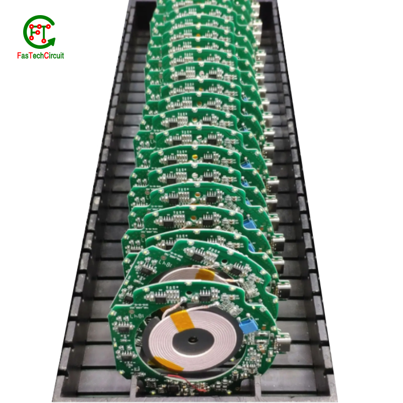
1000w amplifier pcb board
With excellent project management skills, open communication, constant follow-up, and customer-centric values, we will make electronic development run smoothly. High-quality production is even harder to find. All our products comply with international quality standards and our customers come from different markets around the world. For example Bangladesh,Cape Verde,Pakistan,Egypt,Christmas Island,Ghana etc.
| Number of Layers | 4 layer |
| Base Material | gold sinking |
| Board Thickness | 3.2MM |
| Board Size | 265M*604MM |
| Model Number | 4 layer pcb |
| Type | pcb |
| Place of Origin | Original |
| Brand Name | Original |
| Copper Thickness | 3OZ |
| Min. Hole Size | custom made |
| Min. Line Width | custom made |
| Min. Line Spacing | custom made |
| Surface Finishing | custom made |
| Impedance control | +/- 8% |
| Warpage | less than 1% |
| Packaging Details | New and Original, factory sealed packing, it will be pack in one of these packing type: Tube, Tray, Tape and Reel, Tape and Box, Bulk packing, Bag and etc. Please kindly contact us for more details. |
| Supply Ability | 8411 Piece/Pieces per Week |
| Quantity (pieces) | > 10372 |
| Lead time (days) | 11 |
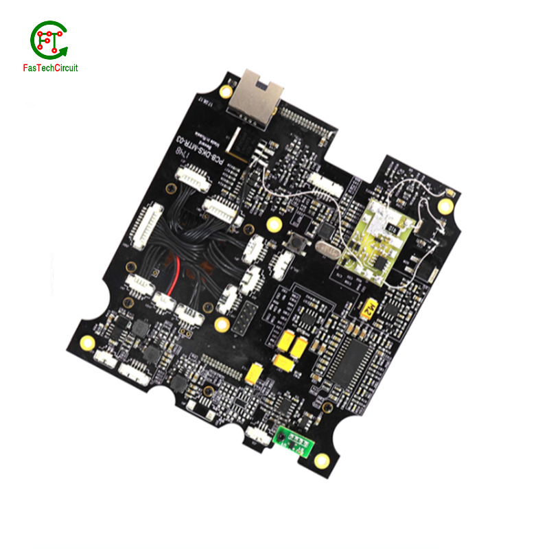
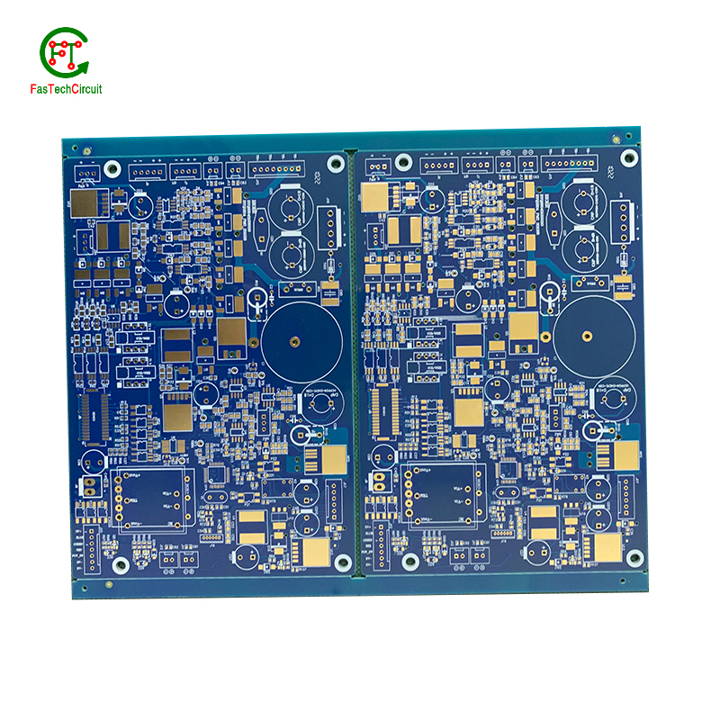
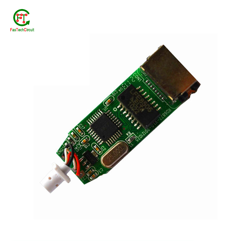
1000w amplifier pcb board bearings FAQs Guide Welcome to our state-of-the-art PCB (Printed Circuit Board) products. We are proud to offer a comprehensive range of high-quality and versatile PCB solutions to meet the constantly evolving needs of the modern electronics industry.Our PCBs are expertly designed and manufactured using the latest technology and advanced techniques, ensuring reliability, durability, and exceptional performance for a wide range of applications. We understand the importance of precision and attention to detail in the production of PCBs and we are committed to meeting stringent quality standards.
2.What is the role of automated optical inspection (AOI) in 1000w amplifier pcb board production?
3.What type of solder is used for 1000w amplifier pcb board assembly?
4.What is the difference between a copper pour and a trace on a 1000w amplifier pcb board?
5.What is the purpose of a solder mask on a 1000w amplifier pcb board?
6.What are some common 1000w amplifier pcb board layout guidelines?
7.What is the minimum thickness of a 1000w amplifier pcb board?
8.How are signal traces routed on a 1000w amplifier pcb board?
9.What is the difference between single-sided, double-sided, and multi-layer 1000w amplifier pcb board?
10.What is the lifespan of a 1000w amplifier pcb board under harsh environmental conditions?
11.What are the most common uses for 1000w amplifier pcb board?
12.What is the purpose of a ground plane on a 1000w amplifier pcb board?
13.What is the standard thickness for copper used in 1000w amplifier pcb boards?
14.What is the minimum size of a through-hole component that can be used on a 1000w amplifier pcb board?
1.What does 1000w amplifier pcb board stand for?
We attach importance to the innovation ability and team spirit of employees, have advanced R & D facilities and laboratories, and have a good quality management system.
PCB stands for Printed Circuit Board.
2.What is the role of automated optical inspection (AOI) in 1000w amplifier pcb board production?
Automated optical inspection (AOI) plays a crucial role in the production of printed circuit boards (PCBs). It is a technology that uses advanced imaging techniques to detect and identify defects or errors on a PCB, such as missing components, incorrect placement, and faulty soldering. AOI has become an essential step in the production process as it helps manufacturers ensure the quality and reliability of their PCBs. By detecting and identifying defects at an early stage, AOI can significantly reduce the number of defects and increase the efficiency of the production process. Furthermore, AOI is able to perform inspections at a much faster rate and with higher accuracy compared to manual inspection, making it an indispensable tool for PCB production.
3.What type of solder is used for 1000w amplifier pcb board assembly?
The most commonly used solder for PCB assembly is a lead-free solder, specifically a tin-silver-copper (SnAgCu) alloy. This type of solder is preferred due to its high melting point, good wetting properties, and compatibility with surface mount technology (SMT) components. Other types of solder that may be used include tin-lead (SnPb) solder and lead-free alternatives such as tin-copper (SnCu) and tin-bismuth (SnBi) alloys. The specific type of solder used may vary depending on the application and industry standards.
4.What is the difference between a copper pour and a trace on a 1000w amplifier pcb board?
We adhere to the principle of quality first and have a complete production quality management system and quality inspection process.
A copper pour and a trace are two common electronic components that are found on a printed circuit board (PCB). A copper pour is a large area of copper that is used to connect multiple components or ground signals together on a PCB. This creates a solid and low resistance pathway for signals to flow. On the other hand, a trace is a thin line of copper used to connect individual components on a PCB. It carries a specific signal from one component to another. Unlike a copper pour, a trace can be designed to carry a specific current and have a specific width to meet the requirements of the circuit.
5.What is the purpose of a solder mask on a 1000w amplifier pcb board?
We have a good reputation and image in the industry. The quality and price advantage of 1000w amplifier pcb board products is an important factor in our hard overseas market.
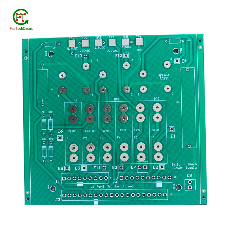
A solder mask is a thin layer of protective material applied to a printed circuit board (PCB) to prevent solder from bridging between conductive traces, pads, or vias during the soldering process. It also helps to protect the PCB from environmental factors such as moisture, dust, and corrosion. Additionally, the solder mask can provide insulation between conductive traces, reducing the risk of short circuits. It also helps to improve the overall appearance of the PCB by providing a uniform and professional finish.
6.What are some common 1000w amplifier pcb board layout guidelines?
We should have a stable supply chain and logistics capabilities, and provide customers with high -quality, low -priced 1000w amplifier pcb board products.
Thermal considerations play a crucial role in the design of printed circuit boards (PCBs). The concept of heat management is critical as excessive heat can lead to reduced performance and potential damage to the electronic components on the board. This is why thermal considerations are carefully taken into account during PCB design. Designers must carefully consider factors such as the size, placement, and orientation of components on the board to ensure efficient heat dissipation. They also need to factor in the type and thickness of the board material, as well as incorporate proper ventilation and heat sinks to prevent overheating. By carefully considering these thermal aspects during the design process, the resulting PCBs can perform optimally and have a longer lifespan.
7.What is the minimum thickness of a 1000w amplifier pcb board?
We are committed to providing personalized solutions and established long -term strategic cooperative relationships with customers.
The minimum thickness of a PCB (printed circuit board) can vary depending on the materials and manufacturing processes used. However, the standard minimum thickness for a single-sided PCB is 0.6mm (0.024 inches) and for a double-sided PCB it is 0.8mm (0.032 inches). Thinner PCBs can be made, but they may be more fragile and have limitations on the components and circuitry that can be used.
8.How are signal traces routed on a 1000w amplifier pcb board?
Signal traces are an essential element of a PCB, responsible for carrying electronic signals between components and ensuring proper communication and functionality of the circuit. To route these traces, designers use specialized software to determine the most efficient and optimal path for each signal, taking into account factors such as signal integrity, trace length, and potential interference. This process involves careful planning, as well as techniques such as vias, ground and power planes, and differential pairs to minimize noise and maintain signal integrity.

9.What is the difference between single-sided, double-sided, and multi-layer 1000w amplifier pcb board?
We have established a good reputation and reliable partnerships within the 1000w amplifier pcb board industry.
Single-sided PCB (Printed Circuit Board) is a type of PCB that has components and traces on only one side of the board. The other side is usually used for soldering and mounting the board onto a larger circuit.
Double-sided PCB is a type of PCB that has components and traces on both sides of the board. The traces on both sides are connected through vias, which are small holes drilled through the board and plated with metal to create an electrical connection.
Multi-layer PCB is a type of PCB that has multiple layers of conductive material and insulating material sandwiched together. The layers are connected through vias, allowing for more complex and compact circuit designs. Multi-layer PCBs are used in more advanced and high-performance electronic devices.
10.What is the lifespan of a 1000w amplifier pcb board under harsh environmental conditions?
The lifespan of a PCB (printed circuit board) under harsh environmental conditions can vary greatly depending on the specific conditions and the quality of the PCB. In general, a well-designed and high-quality PCB can last for 10-20 years under harsh conditions such as extreme temperatures, humidity, and exposure to chemicals or vibrations. However, if the PCB is not properly designed or manufactured, its lifespan can be significantly shorter, potentially lasting only a few years or even months. Factors such as the type of materials used, the thickness of the copper traces, and the quality of the solder joints can also affect the lifespan of a PCB under harsh environmental conditions. Regular maintenance and proper handling can also help extend the lifespan of a PCB.
11.What are the most common uses for 1000w amplifier pcb board?
We enjoy high authority and influence in the industry and continue to innovate products and service models.
Printed circuit boards, or PCBs, are widely used in electronic devices and equipment. They are used in everything from smartphones and computers to household appliances and automotive systems. PCBs are essential components for connecting electrical and electronic components together, providing a robust and reliable platform for digital and analog signals to pass through. Common uses for PCBs include controlling and powering electronic devices, storing and processing data, and providing a means of communication between components. They are also used in various industrial and commercial applications, such as automation and control systems, medical equipment, and aerospace technology. PCBs offer a cost-effective and efficient solution for creating complex electronic circuits, making them a crucial component in modern technology.
12.What is the purpose of a ground plane on a 1000w amplifier pcb board?
I have a comprehensive after -sales service system, which can pay attention to market trends in time and adjust our strategy in a timely manner.
A decoupling capacitor is an essential component on a PCB (Printed Circuit Board) which is used to reduce or eliminate high frequency noise between different components. It acts as a buffer between the power supply and other circuit components, by storing electrical charge and then releasing it when there is a sudden change in the supply voltage. This helps to stabilize the power supply, providing a steady and noise-free flow of electricity to the circuit. Furthermore, decoupling capacitors also help to filter out any unwanted signals that may cause interference or disruptions in the proper functioning of the circuit.
13.What is the standard thickness for copper used in 1000w amplifier pcb boards?
The standard thickness for copper used in PCBs is 1 ounce (oz) or 35 micrometers (µm). However, thicker copper layers such as 2 oz or 3 oz can also be used for higher current carrying capacity or better heat dissipation. The thickness of copper used in a PCB is determined by the design requirements and the intended use of the board.
14.What is the minimum size of a through-hole component that can be used on a 1000w amplifier pcb board?
We continue to invest in research and development and continue to launch innovative products.
The minimum size of a through-hole component that can be used on a PCB depends on the capabilities of the PCB manufacturer and the design requirements of the circuit. Generally, the minimum size for a through-hole component is around 0.2mm in diameter, but some manufacturers may be able to produce smaller sizes. It is important to consult with the manufacturer and consider the design requirements to determine the appropriate size for a through-hole component on a PCB.
RELATED PRODUCTS & SERVICE
pcb board manufacturing How To Contact US
PCB from 1 to 30 layers, HDI, Heavy Copper, Rigid-flex board with "pcb board manufacturing One-Stop" service.

