a dollar pcb design
With excellent project management skills, open communication, constant follow-up, and customer-centric values, we will make electronic development run smoothly. High-quality production is even harder to find. All our products comply with international quality standards and our customers come from different markets around the world. For example Ireland,Botswana,Saint Vincent and the Grenadines etc.
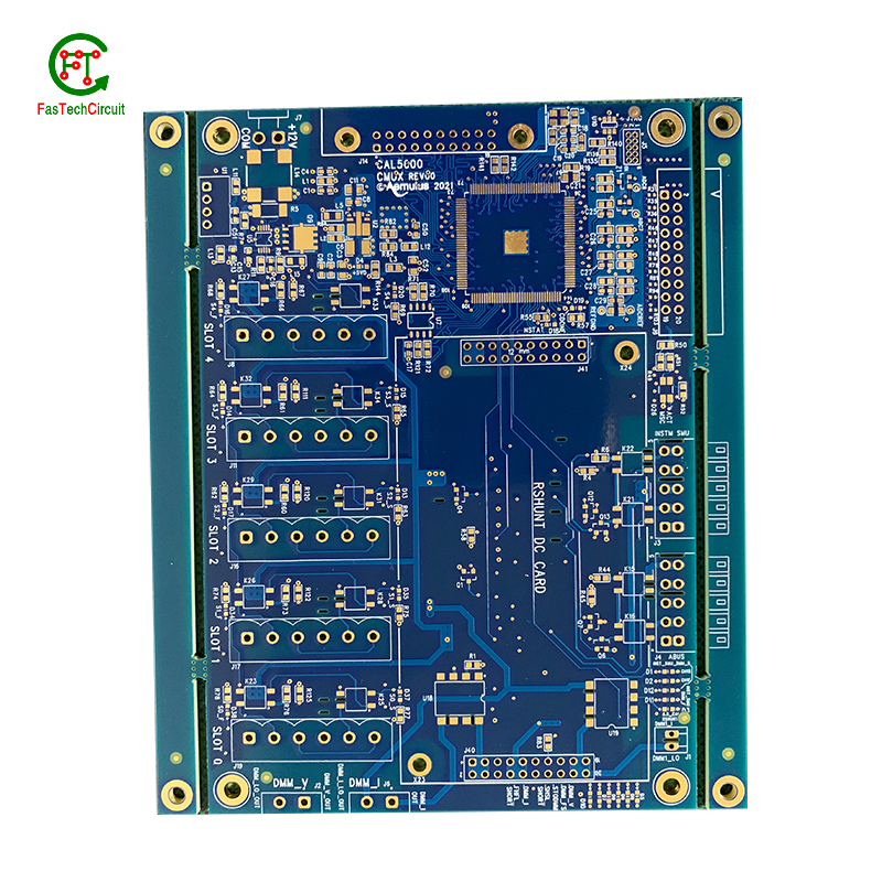
| Number of Layers | 4 layer |
| Base Material | gold sinking |
| Board Thickness | 1.9MM |
| Board Size | 259M*592MM |
| Model Number | 4 layer pcb |
| Type | pcb |
| Place of Origin | Original |
| Brand Name | Original |
| Copper Thickness | 3OZ |
| Min. Hole Size | custom made |
| Min. Line Width | custom made |
| Min. Line Spacing | custom made |
| Surface Finishing | custom made |
| Impedance control | +/- 5% |
| Warpage | less than 1% |
| Packaging Details | New and Original, factory sealed packing, it will be pack in one of these packing type: Tube, Tray, Tape and Reel, Tape and Box, Bulk packing, Bag and etc. Please kindly contact us for more details. |
| Supply Ability | 7062 Piece/Pieces per Week |
| Quantity (pieces) | > 15350 |
| Lead time (days) | 11 |
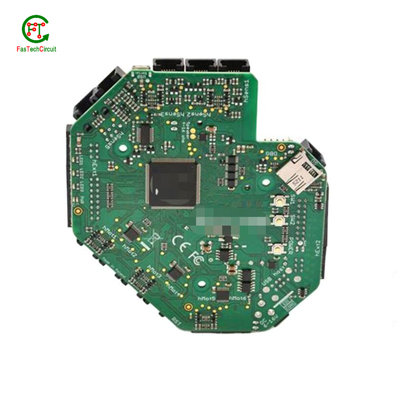
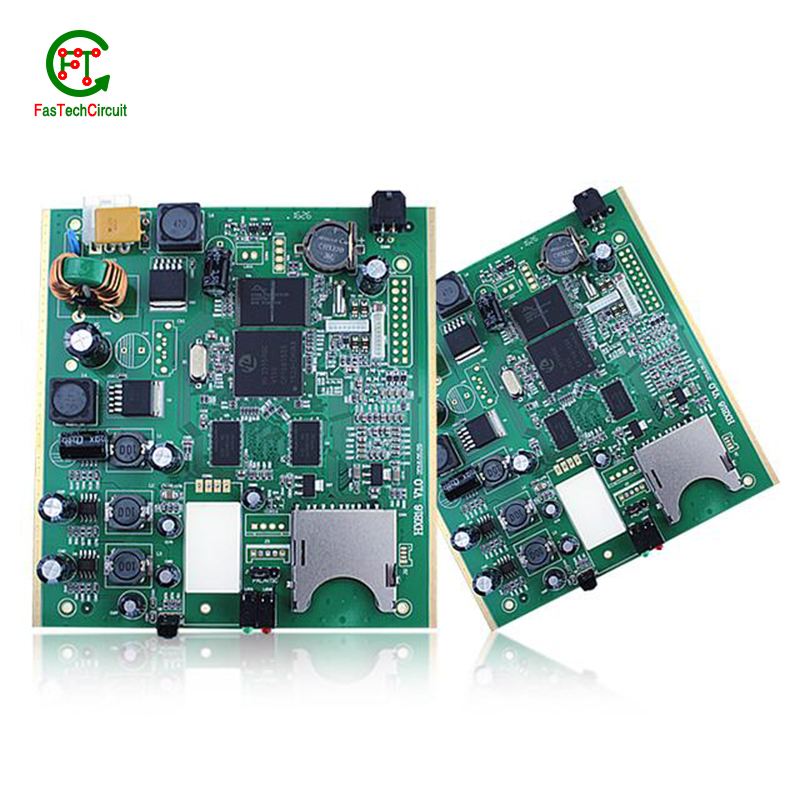
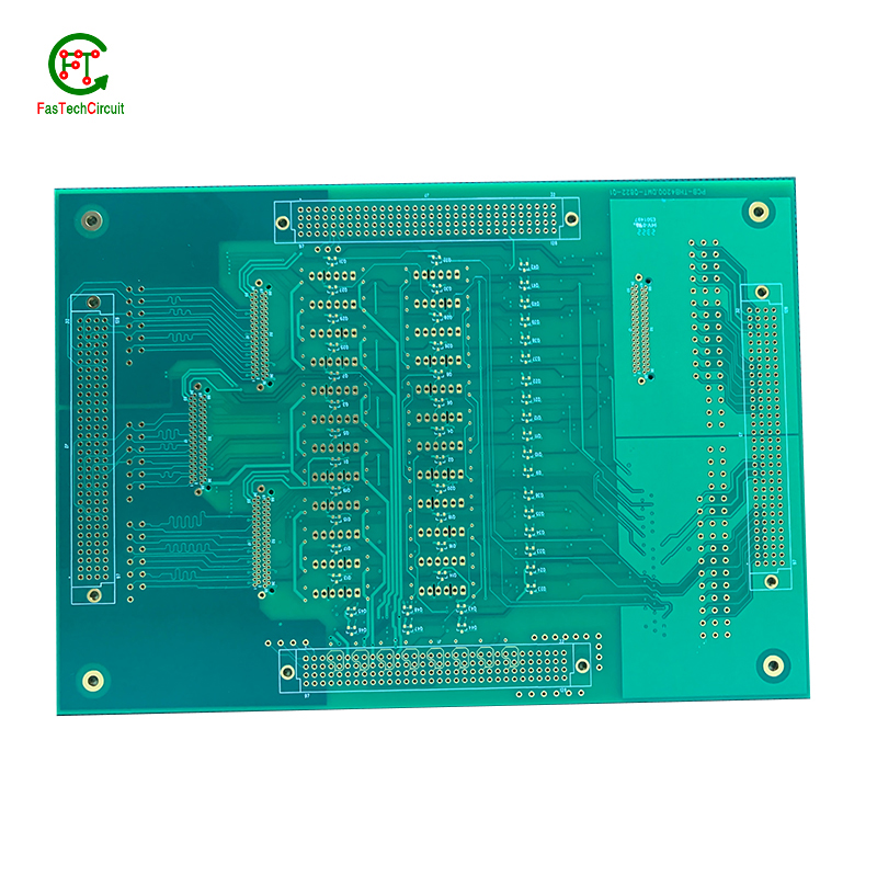
a dollar pcb design bearings FAQs Guide Welcome to our state-of-the-art PCB (Printed Circuit Board) products. We are proud to offer a comprehensive range of high-quality and versatile PCB solutions to meet the constantly evolving needs of the modern electronics industry.Our PCBs are expertly designed and manufactured using the latest technology and advanced techniques, ensuring reliability, durability, and exceptional performance for a wide range of applications. We understand the importance of precision and attention to detail in the production of PCBs and we are committed to meeting stringent quality standards.
2.What is the function of a decoupling capacitor on a a dollar pcb design?
3.What is the standard thickness for copper used in a dollar pcb designs?
4.How are through-hole components soldered onto a a dollar pcb design?
5.What is embedded a dollar pcb design technology?
6.What is the role of automated optical inspection (AOI) in a dollar pcb design production?
7.What is the power rating for a a dollar pcb design?
8.What are the most common uses for a dollar pcb design?
9.Can a dollar pcb designs be used in high voltage applications?
10.What is the maximum operating temperature of a a dollar pcb design?
11.What is the role of a data sheet in a dollar pcb design design?
12.What is the role of silkscreen on a a dollar pcb design?
13.How are a dollar pcb designs tested for quality control?
1.What is the future outlook for a dollar pcb design technology?
Printed Circuit Boards, or PCBs, have been a vital component in electronic devices for decades. They serve as the foundation for the electrical connections and components that make our devices function properly. As technology continues to advance, so does the demand for smaller, faster, and more efficient PCBs. With the rise of IoT and smart devices, the future outlook for PCB technology is promising. It is expected that PCBs will become even more compact and complex, utilizing advanced materials and techniques such as 3D printing and flexible substrates. This will not only improve the performance of electronic devices, but also make them more durable and cost-effective. Furthermore, as sustainability becomes a growing concern, eco-friendly PCB materials and manufacturing processes are being developed to reduce environmental impact. With these advancements, it is safe to say that the future of PCB technology is bright and full of endless possibilities.
2.What is the function of a decoupling capacitor on a a dollar pcb design?
We have rich industry experience and professional knowledge, and have strong competitiveness in the market.
A decoupling capacitor is a type of capacitor that is used to reduce or eliminate noise and interference in electronic circuits. It is typically placed on a PCB (printed circuit board) near the power supply pins of an integrated circuit (IC) or other active component.
The main function of a decoupling capacitor is to provide a stable and clean power supply to the IC or other active component. This is achieved by filtering out high-frequency noise and voltage fluctuations that can be caused by other components on the PCB or external sources.
In addition, a decoupling capacitor also helps to prevent voltage drops and spikes that can occur when the IC or other component suddenly draws a large amount of current. This is especially important for sensitive components that require a stable power supply to function properly.
3.What is the standard thickness for copper used in a dollar pcb designs?
The standard thickness for copper used in PCBs is 1 ounce (oz) or 35 micrometers (µm). However, thicker copper layers such as 2 oz or 3 oz can also be used for higher current carrying capacity or better heat dissipation. The thickness of copper used in a PCB is determined by the design requirements and the intended use of the board.
4.How are through-hole components soldered onto a a dollar pcb design?
Through-hole components are soldered onto a printed circuit board (PCB) using a process called wave soldering. First, the PCB is fitted with all the necessary through-hole components, such as resistors, capacitors, and diodes. Then, the board is passed over a wave of molten solder, which flows through the holes in the PCB and creates a secure connection between the component and the board. The excess solder is removed and the board is inspected to ensure all components are properly soldered. This method of soldering provides a strong and reliable connection for through-hole components, making it a popular choice for electronic assembly.
5.What is embedded a dollar pcb design technology?
Our products & services cover a wide range of areas and meet the needs of different fields.
Embedded PCB technology refers to the integration of electronic components directly onto a printed circuit board (PCB) during the manufacturing process. This allows for a more compact and efficient design, as well as improved reliability and performance. The components are embedded within the layers of the PCB, rather than being mounted on the surface, resulting in a more streamlined and durable product. This technology is commonly used in applications such as smartphones, tablets, and other portable electronic devices.
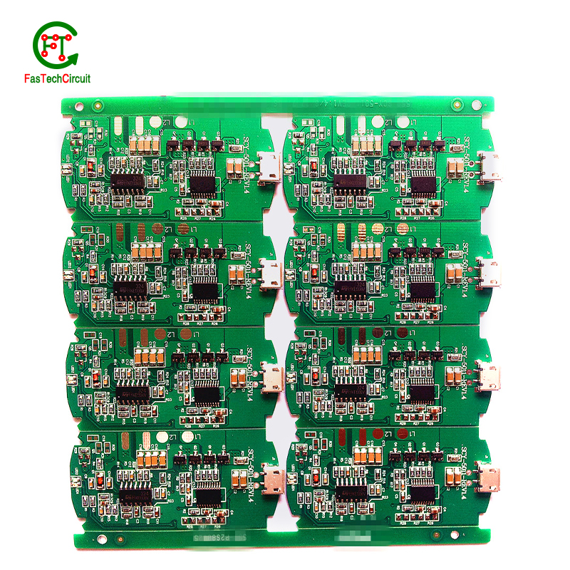
6.What is the role of automated optical inspection (AOI) in a dollar pcb design production?
Automated optical inspection (AOI) plays a crucial role in the production of printed circuit boards (PCBs). It is a technology that uses advanced imaging techniques to detect and identify defects or errors on a PCB, such as missing components, incorrect placement, and faulty soldering. AOI has become an essential step in the production process as it helps manufacturers ensure the quality and reliability of their PCBs. By detecting and identifying defects at an early stage, AOI can significantly reduce the number of defects and increase the efficiency of the production process. Furthermore, AOI is able to perform inspections at a much faster rate and with higher accuracy compared to manual inspection, making it an indispensable tool for PCB production.
7.What is the power rating for a a dollar pcb design?
We maintain a certain amount of R&D investment every year and continuously improve operational efficiency to provide better services to our cooperative customers.
The power rating for a PCB (printed circuit board) can vary greatly depending on its size, design, and intended use. Generally, the power rating for a PCB is determined by the maximum amount of current it can safely handle without overheating or causing damage. This can range from a few milliamps for small, low-power circuits to several amps for larger, high-power circuits. It is important to consult the manufacturer's specifications or consult with an engineer to determine the specific power rating for a particular PCB.
8.What are the most common uses for a dollar pcb design?
We enjoy high authority and influence in the industry and continue to innovate products and service models.
Printed circuit boards, or PCBs, are widely used in electronic devices and equipment. They are used in everything from smartphones and computers to household appliances and automotive systems. PCBs are essential components for connecting electrical and electronic components together, providing a robust and reliable platform for digital and analog signals to pass through. Common uses for PCBs include controlling and powering electronic devices, storing and processing data, and providing a means of communication between components. They are also used in various industrial and commercial applications, such as automation and control systems, medical equipment, and aerospace technology. PCBs offer a cost-effective and efficient solution for creating complex electronic circuits, making them a crucial component in modern technology.
9.Can a dollar pcb designs be used in high voltage applications?
We have advantages in marketing and channel expansion. Suppliers have established good cooperative relations, continuously improved workflows, improved efficiency and productivity, and provided customers with high -quality products and services.
Yes, PCBs (printed circuit boards) can be used in high voltage applications. However, the design and construction of the PCB must be carefully considered to ensure it can withstand the high voltage without causing damage or malfunction. This may include using specialized materials, increasing the spacing between components, and implementing proper insulation and grounding techniques. It is important to consult with a qualified engineer or designer when using PCBs in high voltage applications to ensure safety and reliability.
10.What is the maximum operating temperature of a a dollar pcb design?
We have a professional team that is committed to the innovation and development of a dollar pcb design.
The maximum operating temperature of a PCB (printed circuit board) can vary depending on the materials and components used in its construction. Generally, the maximum operating temperature for a standard FR4 PCB is around 130-140 degrees Celsius. However, specialized materials such as high-temperature laminates or ceramic substrates can withstand higher temperatures up to 200-250 degrees Celsius. The maximum operating temperature of a PCB should always be determined by the manufacturer's specifications and guidelines.
11.What is the role of a data sheet in a dollar pcb design design?
A data sheet is an essential tool for PCB design, providing vital information and specifications for all of the components used in the design process. It contains detailed technical data, such as dimensions, electrical ratings, and performance characteristics, that allow designers to make informed decisions when selecting and placing components on a PCB. By referencing the data sheet, designers can ensure that each component is properly integrated into the overall design, following any necessary guidelines or restrictions. Additionally, data sheets also provide necessary information for the layout and routing of traces on the PCB, ensuring that the design can meet required performance specifications.
12.What is the role of silkscreen on a a dollar pcb design?
Being one of the top a dollar pcb design manufacturers in China, We attach great importance to this detail.
Silkscreen, also known as legend or nomenclature, is a vital component of a printed circuit board (PCB). It is the layer of text and symbols that are printed on the surface of the PCB to provide essential information for component placement and identification. The silkscreen plays a crucial role in the manufacturing process of PCBs, as it helps to ensure the accuracy and functionality of the final product. By indicating component locations, values, and reference designators, the silkscreen serves as a guide for the assembly and soldering of electronic components. Additionally, it also provides important information for maintenance and troubleshooting purposes.
13.How are a dollar pcb designs tested for quality control?
We have broad development space in domestic and foreign markets. a dollar pcb design have great advantages in terms of price, quality, and delivery date.
PCB (Printed Circuit Board) testing is a critical step in the quality control process of electronic products. It ensures that all components and connections on the board are functioning correctly and that the PCB meets the required standards and specifications.
The testing process typically starts with a visual inspection to identify any visible defects, such as incorrect soldering or damaged components. Next, electrical testing is conducted to check the functionality of each individual component and the overall circuit.
One common method of testing is the use of a test fixture, which applies signals to the PCB and checks for correct responses. Other methods include automated optical inspection (AOI) and in-circuit testing (ICT).
Once the initial testing is completed, the PCB may undergo environmental testing to simulate real-life conditions and ensure its reliability and durability. This includes temperature and humidity cycling, vibration and shock testing, and more.
RELATED PRODUCTS & SERVICE
pcb board manufacturing How To Contact US
PCB from 1 to 30 layers, HDI, Heavy Copper, Rigid-flex board with "pcb board manufacturing One-Stop" service.
