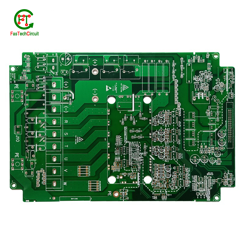
8051 microcontroller pcb board
| Model Number | customized PCBA |
| Type | pcba |
| Place of Origin | Guangdong, China |
| Brand Name | none |
| Copper Thickness | 1 oz |
| Supplier Type | OEM |
| Application | Electronics Device |
| Service | One-step Service |
| Layer | 1-33layers |
| Solder mask color | Blue.green.red.black.white.etc |
| Testing Service | 100% |
| Component size | 0201-1153mm |
| Component max height | 34mm |
| Min lead pitch | 0.2mm |
| Min BGA ball pitch | 0.6mm |
| Max PCB size | 558x516mm |
| Packaging Details | Vacuum package for bare PCB and ESD package for PCBA Printed Circuit Board Factory FPC Board PCBA Companies PCBA Assembly |
| Supply Ability | 49384 Piece/Pieces per Week |
| Quantity (pieces) | > 798 |
| Lead time (days) | 11 |
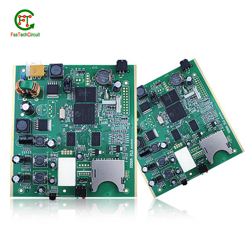
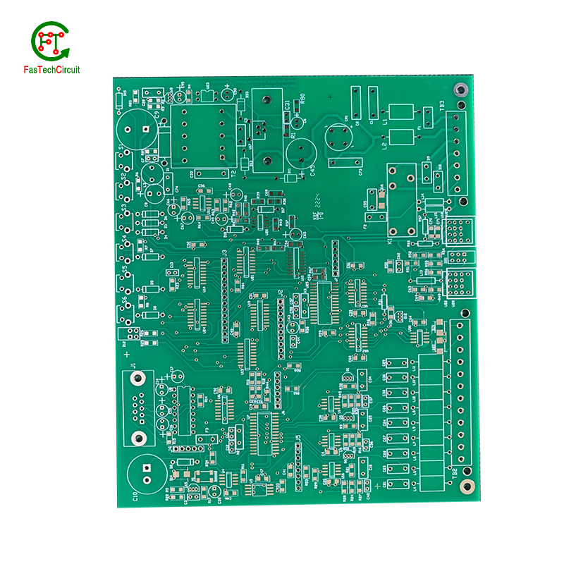
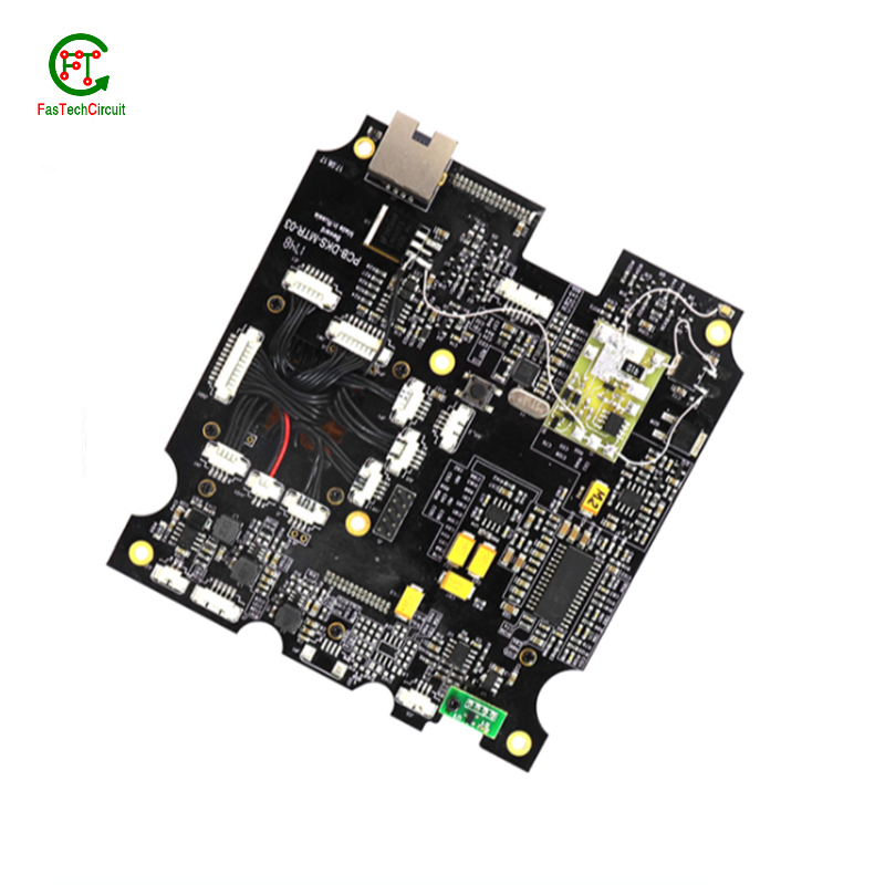
8051 microcontroller pcb board bearings FAQs Guide Welcome to our state-of-the-art PCB (Printed Circuit Board) products. We are proud to offer a comprehensive range of high-quality and versatile PCB solutions to meet the constantly evolving needs of the modern electronics industry.Our PCBs are expertly designed and manufactured using the latest technology and advanced techniques, ensuring reliability, durability, and exceptional performance for a wide range of applications. We understand the importance of precision and attention to detail in the production of PCBs and we are committed to meeting stringent quality standards.
2.How are high-speed/high-frequency 8051 microcontroller pcb board tested and validated?
3.What is the typical lifespan of a 8051 microcontroller pcb board?
4.What is the difference between a gold-plated and a tin-plated 8051 microcontroller pcb board?
5.Are 8051 microcontroller pcb board recyclable?
6.How are signal integrity issues addressed in 8051 microcontroller pcb board design?
7.How are through-hole components soldered onto a 8051 microcontroller pcb board?
8.What is the role of a data sheet in 8051 microcontroller pcb board design?
9.What is the purpose of a solder mask on a 8051 microcontroller pcb board?
10.What is the power rating for a 8051 microcontroller pcb board?
11.What is the difference between a copper pour and a trace on a 8051 microcontroller pcb board?
12.Can 8051 microcontroller pcb boards be used in high-frequency applications?
13.What is the difference between a diode and a capacitor?
1.What types of 8051 microcontroller pcb boards are there?
As one of the 8051 microcontroller pcb board market leaders, we are known for innovation and reliability.
There are several types of PCBs, including single-sided, double-sided, multi-layer, and flexible PCBs. Single-sided PCBs have components mounted on one side and conductive traces on the other. Double-sided PCBs have components mounted on both sides with conductive traces connecting them. Multi-layer PCBs have several layers of conductive traces and insulating material sandwiched together. Flexible PCBs are made from a flexible plastic material, allowing them to bend and twist for use in applications where traditional rigid PCBs are not suitable. Each type of PCB serves a different purpose and can be used in a variety of electronic devices and applications.
2.How are high-speed/high-frequency 8051 microcontroller pcb board tested and validated?
Testing and validation are essential steps in the production process of high-speed and high-frequency printed circuit boards (PCBs). These specialized types of PCBs are used in a wide range of industries, including telecommunications, aerospace, and automotive, and require precision and reliability in their performance.
The testing and validation process for high-speed/high-frequency PCBs involves several steps to ensure that the final product meets the required specifications. This starts with design simulation and analysis using specialized software to verify the layout and electrical characteristics of the PCB.
Once the design is confirmed, prototype PCBs are manufactured and subjected to various tests, including signal integrity and power integrity tests. These tests evaluate the electrical performance of the PCB, such as its ability to transmit signals at high speeds and maintain signal integrity.
In addition to electrical tests, environmental and mechanical tests are also performed to assess the durability and reliability of the PCB under different conditions, such as temperature changes and mechanical stress.
The final step in the testing and validation process is the inspection and analysis of the tested PCBs. This involves a detailed review of the test results and any necessary modifications to meet the required specifications.
3.What is the typical lifespan of a 8051 microcontroller pcb board?
8051 microcontroller pcb board is not a product only, but also can help you comes to money-making.
The typical lifespan of a PCB (printed circuit board) can vary greatly depending on various factors such as the quality of materials used, environmental conditions, and usage. In general, a well-designed and properly manufactured PCB can last for 10-20 years or more. However, some PCBs may fail prematurely due to factors such as corrosion, thermal stress, or mechanical damage. Regular maintenance and proper handling can also extend the lifespan of a PCB.
4.What is the difference between a gold-plated and a tin-plated 8051 microcontroller pcb board?
A gold-plated PCB (Printed Circuit Board) is a type of PCB that has a thin layer of gold coating on its surface. This layer is added through a process called electroplating and is commonly used to protect the PCB components from corrosion and increase the conductivity. On the other hand, a tin-plated PCB has a layer of tin coating on its surface, which is also applied through electroplating. Unlike gold plating, tin plating is mainly used to prevent oxidization and improve solderability.
5.Are 8051 microcontroller pcb board recyclable?
We have been working hard to improve service quality and meet customer needs.
Yes, PCBs (printed circuit boards) are recyclable. They can be broken down and the individual components can be reused or repurposed. However, the recycling process can be complex and requires specialized equipment and techniques. It is important to properly dispose of PCBs to prevent environmental contamination and health hazards.
6.How are signal integrity issues addressed in 8051 microcontroller pcb board design?
We focus on our customers' needs and strive to meet their expectations, so we take this very seriously.
Signal integrity issues are a common concern in PCB design, as they can greatly affect the performance and reliability of electronic systems. These issues arise from high-speed signal transmissions on the board, which can result in degraded signals, data errors, and even system failures. In order to address these issues, PCB designers must consider various factors such as layout, routing, and component placement to ensure proper signal integrity. This involves implementing signal protection measures such as controlled impedance routing, signal shielding, and minimizing signal crosstalk. Additionally, designers may use simulation and analysis tools to identify and resolve any potential signal integrity problems before the PCB goes into production. By carefully addressing signal integrity issues in the design phase, PCBs can achieve optimal performance and functionality.
7.How are through-hole components soldered onto a 8051 microcontroller pcb board?
Through-hole components are soldered onto a printed circuit board (PCB) using a process called wave soldering. First, the PCB is fitted with all the necessary through-hole components, such as resistors, capacitors, and diodes. Then, the board is passed over a wave of molten solder, which flows through the holes in the PCB and creates a secure connection between the component and the board. The excess solder is removed and the board is inspected to ensure all components are properly soldered. This method of soldering provides a strong and reliable connection for through-hole components, making it a popular choice for electronic assembly.
8.What is the role of a data sheet in 8051 microcontroller pcb board design?
A data sheet is an essential tool for PCB design, providing vital information and specifications for all of the components used in the design process. It contains detailed technical data, such as dimensions, electrical ratings, and performance characteristics, that allow designers to make informed decisions when selecting and placing components on a PCB. By referencing the data sheet, designers can ensure that each component is properly integrated into the overall design, following any necessary guidelines or restrictions. Additionally, data sheets also provide necessary information for the layout and routing of traces on the PCB, ensuring that the design can meet required performance specifications.
9.What is the purpose of a solder mask on a 8051 microcontroller pcb board?
We have a good reputation and image in the industry. The quality and price advantage of 8051 microcontroller pcb board products is an important factor in our hard overseas market.
A solder mask is a thin layer of protective material applied to a printed circuit board (PCB) to prevent solder from bridging between conductive traces, pads, or vias during the soldering process. It also helps to protect the PCB from environmental factors such as moisture, dust, and corrosion. Additionally, the solder mask can provide insulation between conductive traces, reducing the risk of short circuits. It also helps to improve the overall appearance of the PCB by providing a uniform and professional finish.
10.What is the power rating for a 8051 microcontroller pcb board?
We maintain a certain amount of R&D investment every year and continuously improve operational efficiency to provide better services to our cooperative customers.
The power rating for a PCB (printed circuit board) can vary greatly depending on its size, design, and intended use. Generally, the power rating for a PCB is determined by the maximum amount of current it can safely handle without overheating or causing damage. This can range from a few milliamps for small, low-power circuits to several amps for larger, high-power circuits. It is important to consult the manufacturer's specifications or consult with an engineer to determine the specific power rating for a particular PCB.
11.What is the difference between a copper pour and a trace on a 8051 microcontroller pcb board?
We adhere to the principle of quality first and have a complete production quality management system and quality inspection process.
A copper pour and a trace are two common electronic components that are found on a printed circuit board (PCB). A copper pour is a large area of copper that is used to connect multiple components or ground signals together on a PCB. This creates a solid and low resistance pathway for signals to flow. On the other hand, a trace is a thin line of copper used to connect individual components on a PCB. It carries a specific signal from one component to another. Unlike a copper pour, a trace can be designed to carry a specific current and have a specific width to meet the requirements of the circuit.
12.Can 8051 microcontroller pcb boards be used in high-frequency applications?
Our mission is to provide customers with the best solutions for 8051 microcontroller pcb board.
Yes, PCBs (printed circuit boards) can be used in high-frequency applications. However, the design and construction of the PCB must be carefully considered to ensure optimal performance at high frequencies. This includes using specialized materials, such as high-frequency laminates, and implementing proper grounding and shielding techniques. Additionally, the layout and routing of the PCB must be optimized to minimize signal loss and interference.
13.What is the difference between a diode and a capacitor?
We have a first -class management team, and we pay attention to teamwork to achieve common goals.
A diode is an electronic component that allows current to flow in only one direction. It has two terminals, an anode and a cathode, and works by allowing current to flow from the anode to the cathode, but not in the reverse direction.
A capacitor, on the other hand, is an electronic component that stores electrical energy in an electric field. It has two conductive plates separated by an insulating material, and when a voltage is applied, one plate accumulates a positive charge and the other accumulates a negative charge. This allows the capacitor to store energy and release it when needed.
RELATED PRODUCTS & SERVICE
pcb board manufacturing How To Contact US
PCB from 1 to 30 layers, HDI, Heavy Copper, Rigid-flex board with "pcb board manufacturing One-Stop" service.

