1000 watt amplifier pcb circuit
FasTechCircuit's products cover single-panel, double-panel, multi-layer boards, rigid boards, flexible boards, hybrid (rigid-soft) boards and other types. According to customer needs and application fields, we can provide PCB products of different materials and processes, such as FR-4, aluminum substrates, ceramic substrates, etc. At the same time, we can also provide a variety of surface treatment processes according to customer needs, such as OSP, HASL, ENIG, etc., to ensure the reliability and stability of the circuit board. We also provide non-standard customization services and can customize production according to the special requirements provided by customers to meet their personalized needs.
FasTechCircuit's printed circuit board products are widely used in communication equipment, industrial control, consumer electronics, computers and peripheral equipment, medical equipment, aerospace and other fields. Our products undergo strict quality control, have high precision, high reliability and stability, and can meet customers' high requirements for electronic products. Our products are very popular in Netherlands,Kazakhstan,Kenya, the United States and Japan. Won high praise from customers.
| Base Material | FR-4/CEM-1/CEM-3/Polyimild/PTFE/Rogers |
| Board Thickness | 0.1-8mm |
| Model Number | Custom PCB & PCB Assembly |
| Type | Aluminum PCB |
| Brand Name | FC |
| Copper Thickness | 0.5-2mil(6-54um) |
| Min. Hole Size | 0.1mm(4mil)for HDI / 0.15mm(6mil) |
| Min. Line Width | 0.075mm/0.075mm(3mil/3mil) |
| Min. Line Spacing | 0.003'' |
| Surface Finishing | HASL/OSP/Ag/ENIG/ENEPIG/Immersion silver/Tin |
| Board Size | Custom |
| Model Number | Customized |
| Base Material | FR4 Aluminum CEM-1 94V0 |
| Surface Finishing | HASLENIG OSP |
| Number of layer | 1-14layer |
| Other service | Components purchasing and assem |
| ly Solder mask | White Black Green Blue,Red,etc. |
| Dsign service | Available |
| Testing | Function testing |
| Certificate | RoHS, ISO/TS16949, ISO9001 |
| Name | High Quality led light aluminum pcb printed circuit board |
| Packaging Details | Vaccum package and standard carton outside High Quality led light aluminum pcb printed circuit board |
| Supply Ability | 52563 Square Meter/Square Meters per Month |
| Quantity (pieces) | > 26090 |
| Lead time (days) | 14 |
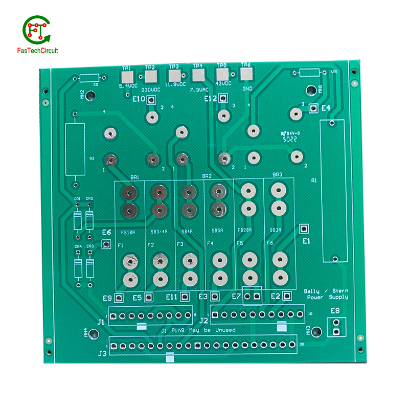
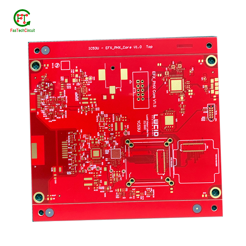
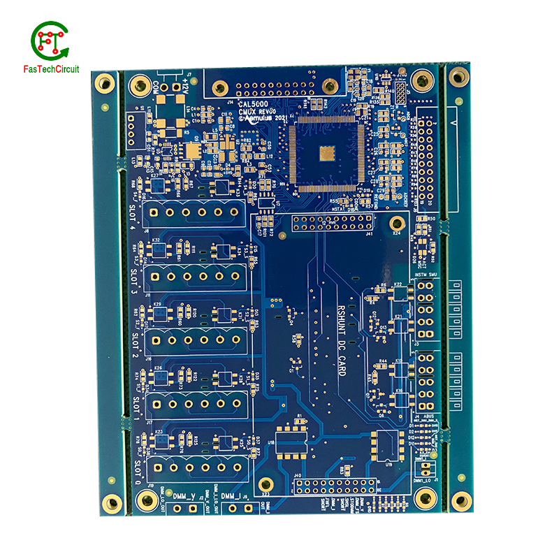
1000 watt amplifier pcb circuit bearings FAQs Guide Welcome to our state-of-the-art PCB (Printed Circuit Board) products. We are proud to offer a comprehensive range of high-quality and versatile PCB solutions to meet the constantly evolving needs of the modern electronics industry.Our PCBs are expertly designed and manufactured using the latest technology and advanced techniques, ensuring reliability, durability, and exceptional performance for a wide range of applications. We understand the importance of precision and attention to detail in the production of PCBs and we are committed to meeting stringent quality standards.
2.How are holes drilled into a 1000 watt amplifier pcb circuit?
3.What materials are used to make a 1000 watt amplifier pcb circuit?
4.What is the standard thickness for copper used in 1000 watt amplifier pcb circuits?
5.What is the role of vias on a 1000 watt amplifier pcb circuit?
6.What is the difference between an analog and a digital signal on a 1000 watt amplifier pcb circuit?
7.What is the minimum size of a through-hole component that can be used on a 1000 watt amplifier pcb circuit?
8.How are components attached to a 1000 watt amplifier pcb circuit?
9.What are the most common uses for 1000 watt amplifier pcb circuit?
10.What is the purpose of a solder mask on a 1000 watt amplifier pcb circuit?
11.What are the advantages of using a 1000 watt amplifier pcb circuit?
12.What is the role of a data sheet in 1000 watt amplifier pcb circuit design?
13.How are thermal considerations taken into account during 1000 watt amplifier pcb circuit design?
1.How are 1000 watt amplifier pcb circuit used in medical devices?
Printed Circuit Boards (PCBs) are essential components used in a wide range of medical devices, playing a crucial role in both diagnostic and treatment equipment. These devices require reliable and precise circuitry to accurately collect and process data, deliver therapies, and regulate medical procedures. PCBs are used in equipment such as MRI machines, pacemakers, defibrillators, and monitors, where their small size and high density make them ideal for compact and portable designs. In addition, PCBs are also used in medical implants, enabling a safe and secure connection between the device and the body. With their advanced technology, PCBs continue to be an integral part of the medical industry, ensuring the effectiveness and success of various medical procedures and treatments.
2.How are holes drilled into a 1000 watt amplifier pcb circuit?
We actively participate in the 1000 watt amplifier pcb circuit industry associations and organization activities. The corporate social responsibility performed well, and the focus of brand building and promotion.
Drilling holes into printed circuit boards (PCBs) is a critical part of the PCB manufacturing process. These holes are used for mounting electronic components and for creating electrical connections between different layers of the board. There are two main methods for drilling holes into a PCB – mechanical drilling and laser drilling. Mechanical drilling involves using a high speed drill bit to physically drill through the board, while laser drilling uses a high-powered laser to vaporize the material and create the holes. Both methods have their own advantages and are often used in combination to achieve the desired hole sizes and precision. Regardless of the method, the holes are carefully planned and executed to ensure the successful production of a high-quality PCB.
3.What materials are used to make a 1000 watt amplifier pcb circuit?
We have advanced production equipment and technology to meet the needs of customers, and can provide customers with high quality, low priced 1000 watt amplifier pcb circuit products.
A PCB, or printed circuit board, is typically made of a non-conductive material such as fiberglass or composite epoxy resin. This material acts as a base for a thin layer of copper foil, which is then etched to create the desired circuit pattern. Other common materials used in the production of PCBs include solder mask, a polymer layer used to insulate and protect the copper traces, and silkscreen, which is used to label and identify the different components on the PCB. In addition, various electronic components such as resistors, capacitors, and diodes are also mounted onto the PCB to form a functional electronic circuit. Other potential materials used in the production of PCBs include metal core, ceramics, and conductive ink, depending on the specific design and requirements of the circuit.
4.What is the standard thickness for copper used in 1000 watt amplifier pcb circuits?
The standard thickness for copper used in PCBs is 1 ounce (oz) or 35 micrometers (µm). However, thicker copper layers such as 2 oz or 3 oz can also be used for higher current carrying capacity or better heat dissipation. The thickness of copper used in a PCB is determined by the design requirements and the intended use of the board.
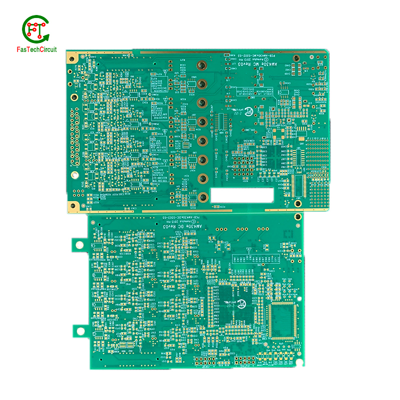
5.What is the role of vias on a 1000 watt amplifier pcb circuit?
Our company has many years of 1000 watt amplifier pcb circuit experience and expertise.
Vias play a crucial role in connecting different layers of a printed circuit board (PCB). These small, plated holes act as conductive paths, allowing signals and power to pass through the board and reach various components. Vias are also essential for routing traces from one layer to another, optimizing the layout and reducing the size and complexity of the board. Additionally, vias provide structural support and improve thermal management by facilitating heat dissipation.
6.What is the difference between an analog and a digital signal on a 1000 watt amplifier pcb circuit?
An analog signal is a continuous signal that varies in amplitude and frequency over time. It can take on any value within a given range and is typically represented by a smooth, continuous waveform. Analog signals are used to transmit information such as audio, video, and sensor data.
A digital signal, on the other hand, is a discrete signal that can only take on a limited number of values. It is represented by a series of binary digits (0s and 1s) and can only have two states: on or off. Digital signals are used to transmit information in the form of data and are commonly used in digital electronics such as computers and smartphones.
On a PCB, the main difference between analog and digital signals lies in the way they are processed and transmitted. Analog signals require specialized components such as amplifiers and filters to maintain their integrity, while digital signals can be processed and transmitted using digital logic circuits. Additionally, analog signals are more susceptible to noise and interference, while digital signals are more immune to these factors.
7.What is the minimum size of a through-hole component that can be used on a 1000 watt amplifier pcb circuit?
We continue to invest in research and development and continue to launch innovative products.
The minimum size of a through-hole component that can be used on a PCB depends on the capabilities of the PCB manufacturer and the design requirements of the circuit. Generally, the minimum size for a through-hole component is around 0.2mm in diameter, but some manufacturers may be able to produce smaller sizes. It is important to consult with the manufacturer and consider the design requirements to determine the appropriate size for a through-hole component on a PCB.
8.How are components attached to a 1000 watt amplifier pcb circuit?
We adhere to the principle of integrity and transparency, and establish long -term relationships with partners, and we attach great importance to this detail.
eads or pins of the component and melting solder onto them, whicComponents are attached to a PCB (printed circuit board) through a process called soldering. This involves heating the metal lh then solidifies and creates a strong electrical and mechanical connection between the component and the PCB. There are two main methods of soldering components onto a PCB:
1. Through-hole soldering: This method involves inserting the leads or pins of the component through pre-drilled holes on the PCB and soldering them on the opposite side of the board. This method is commonly used for larger components such as resistors, capacitors, and integrated circuits.
2. Surface mount soldering: This method involves soldering the component directly onto the surface of the PCB, without the need for pre-drilled holes. This is done using specialized equipment such as a soldering iron or a reflow oven. Surface mount components are smaller in size and are commonly used for more complex and compact electronic devices.
9.What are the most common uses for 1000 watt amplifier pcb circuit?
We enjoy high authority and influence in the industry and continue to innovate products and service models.
Printed circuit boards, or PCBs, are widely used in electronic devices and equipment. They are used in everything from smartphones and computers to household appliances and automotive systems. PCBs are essential components for connecting electrical and electronic components together, providing a robust and reliable platform for digital and analog signals to pass through. Common uses for PCBs include controlling and powering electronic devices, storing and processing data, and providing a means of communication between components. They are also used in various industrial and commercial applications, such as automation and control systems, medical equipment, and aerospace technology. PCBs offer a cost-effective and efficient solution for creating complex electronic circuits, making them a crucial component in modern technology.
10.What is the purpose of a solder mask on a 1000 watt amplifier pcb circuit?
We have a good reputation and image in the industry. The quality and price advantage of 1000 watt amplifier pcb circuit products is an important factor in our hard overseas market.
A solder mask is a thin layer of protective material applied to a printed circuit board (PCB) to prevent solder from bridging between conductive traces, pads, or vias during the soldering process. It also helps to protect the PCB from environmental factors such as moisture, dust, and corrosion. Additionally, the solder mask can provide insulation between conductive traces, reducing the risk of short circuits. It also helps to improve the overall appearance of the PCB by providing a uniform and professional finish.
11.What are the advantages of using a 1000 watt amplifier pcb circuit?
We are centered on customers and always pay attention to customers' needs for 1000 watt amplifier pcb circuit products.
There are several advantages of using a PCB (Printed Circuit Board). Firstly, a PCB provides a compact and organized layout for electronic components, which makes it easier for technicians to troubleshoot and repair any issues. Secondly, it reduces the chances of loose connections and short circuits, which can be a major safety concern. Thirdly, PCBs are cost-effective and can be easily mass-produced, making them a popular choice for large-scale production. Additionally, they offer durability and stability, ensuring long-lasting performance. Finally, PCBs also allow for easy integration of new components, making it easier to upgrade or modify the electronic devices.
12.What is the role of a data sheet in 1000 watt amplifier pcb circuit design?
A data sheet is an essential tool for PCB design, providing vital information and specifications for all of the components used in the design process. It contains detailed technical data, such as dimensions, electrical ratings, and performance characteristics, that allow designers to make informed decisions when selecting and placing components on a PCB. By referencing the data sheet, designers can ensure that each component is properly integrated into the overall design, following any necessary guidelines or restrictions. Additionally, data sheets also provide necessary information for the layout and routing of traces on the PCB, ensuring that the design can meet required performance specifications.
13.How are thermal considerations taken into account during 1000 watt amplifier pcb circuit design?
As one of the top 1000 watt amplifier pcb circuit manufacturers in China, we take this very seriously.
Thermal considerations are crucial in the design of printed circuit boards (PCB), as excessive heat can greatly affect the performance and lifespan of electronic components. PCB design engineers must carefully consider thermal management strategies, such as proper placement of heat-generating components, effective heat dissipation techniques, and optimal selection of materials. Thermal simulations and analysis are also commonly used to evaluate and optimize the PCB design to ensure that the temperature of the PCB and its components are within safe limits. By taking into account these thermal considerations, the finished PCB can perform reliably and efficiently, ensuring the overall quality and function of electronic devices.
RELATED PRODUCTS & SERVICE
pcb board manufacturing How To Contact US
PCB from 1 to 30 layers, HDI, Heavy Copper, Rigid-flex board with "pcb board manufacturing One-Stop" service.

