cell phone jammer pcb layout
Our geographical location enables us to offer competitive prices because in Shenzhen, we have abundant parts resources and convenient transportation. Our products are widely used in consumer electronics, telecommunications, medical, petroleum and other industries. All our products comply with international quality standards and our customers come from different markets around the world. For example Honduras,Micronesia, Federated States of,Croatia etc.
| Base Material | FR-4/CEM-1/CEM-3/Polyimild/PTFE/Rogers |
| Board Thickness | 0.2-3mm |
| Model Number | Custom PCB & PCB Assembly |
| Type | Aluminum PCB |
| Brand Name | FC |
| Copper Thickness | 0.5-2mil(13-56um) |
| Min. Hole Size | 0.1mm(4mil)for HDI / 0.15mm(6mil) |
| Min. Line Width | 0.075mm/0.075mm(3mil/3mil) |
| Min. Line Spacing | 0.003'' |
| Surface Finishing | HASL/OSP/Ag/ENIG/ENEPIG/Immersion silver/Tin |
| Board Size | Custom |
| Model Number | Customized |
| Base Material | FR4 Aluminum CEM-1 94V0 |
| Surface Finishing | HASLENIG OSP |
| Number of layer | 1-19layer |
| Other service | Components purchasing and assem |
| ly Solder mask | White Black Green Blue,Red,etc. |
| Dsign service | Available |
| Testing | Function testing |
| Certificate | RoHS, ISO/TS16949, ISO9001 |
| Name | High Quality led light aluminum pcb printed circuit board |
| Packaging Details | Vaccum package and standard carton outside High Quality led light aluminum pcb printed circuit board |
| Supply Ability | 54253 Square Meter/Square Meters per Month |
| Quantity (pieces) | > 14016 |
| Lead time (days) | 7 |
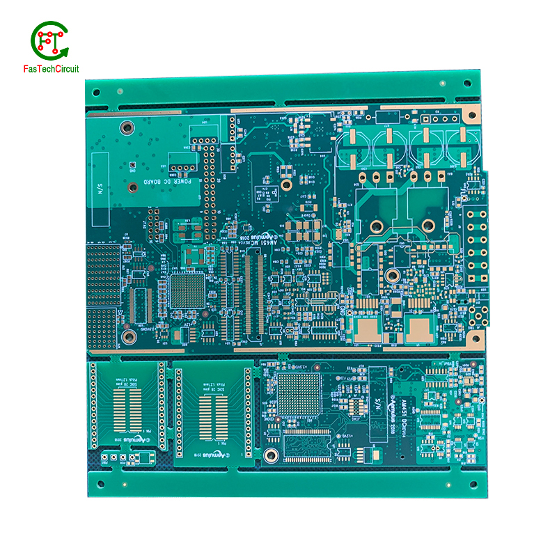
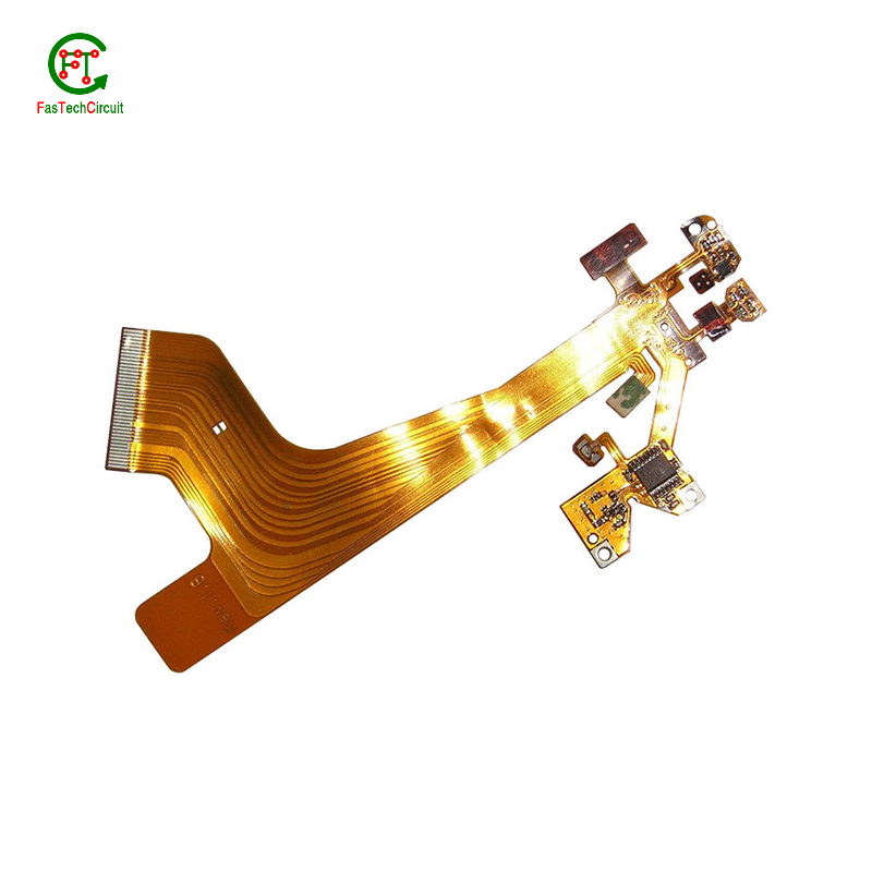
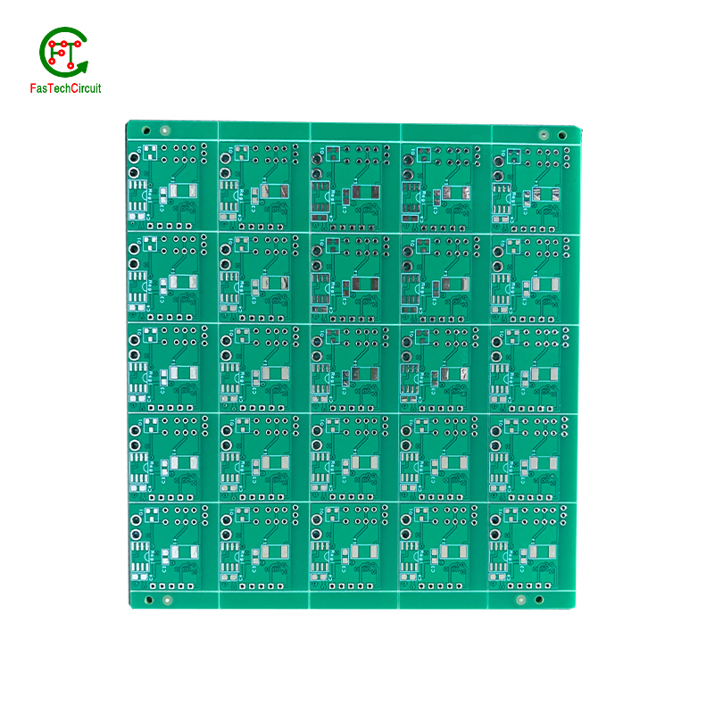
cell phone jammer pcb layout bearings FAQs Guide Welcome to our state-of-the-art PCB (Printed Circuit Board) products. We are proud to offer a comprehensive range of high-quality and versatile PCB solutions to meet the constantly evolving needs of the modern electronics industry.Our PCBs are expertly designed and manufactured using the latest technology and advanced techniques, ensuring reliability, durability, and exceptional performance for a wide range of applications. We understand the importance of precision and attention to detail in the production of PCBs and we are committed to meeting stringent quality standards.
2.What is the function of a resistor on a cell phone jammer pcb layout?
3.What is the purpose of a cell phone jammer pcb layout?
4.How are cell phone jammer pcb layout used in medical devices?
5.What is the maximum operating temperature of a cell phone jammer pcb layout?
6.What is the power rating for a cell phone jammer pcb layout?
7.Can cell phone jammer pcb layouts be used for high-speed data transmission?
8.How are signal traces routed on a cell phone jammer pcb layout?
9.How are power and ground planes connected on a cell phone jammer pcb layout?
10.What techniques are used for reducing electromagnetic interference (EMI) on a cell phone jammer pcb layout?
11.Can cell phone jammer pcb layouts be used in automotive applications?
12.What is the maximum size of a cell phone jammer pcb layout?
13.What software is used for cell phone jammer pcb layout design?
14.How are high-frequency signals handled on a cell phone jammer pcb layout?
1.What is the role of automated optical inspection (AOI) in cell phone jammer pcb layout production?
Automated optical inspection (AOI) plays a crucial role in the production of printed circuit boards (PCBs). It is a technology that uses advanced imaging techniques to detect and identify defects or errors on a PCB, such as missing components, incorrect placement, and faulty soldering. AOI has become an essential step in the production process as it helps manufacturers ensure the quality and reliability of their PCBs. By detecting and identifying defects at an early stage, AOI can significantly reduce the number of defects and increase the efficiency of the production process. Furthermore, AOI is able to perform inspections at a much faster rate and with higher accuracy compared to manual inspection, making it an indispensable tool for PCB production.
2.What is the function of a resistor on a cell phone jammer pcb layout?
We are a new cell phone jammer pcb layout manufacturer.
The ground plane on a printed circuit board (PCB) serves as a reference point for the electrical signals that flow throughout the circuit. It is typically a large area of copper that is connected to the negative terminal of the power supply and serves as a low-impedance return path for current. Its main purpose is to provide a stable and uniform ground connection for the components on the PCB, helping to reduce electromagnetic interference and ensuring proper signal grounding. Without a ground plane, the circuit may experience noise and other unwanted effects, potentially causing malfunctions or disruptions in its functionality. Therefore, the ground plane plays a crucial role in ensuring the overall performance and reliability of a PCB.
3.What is the purpose of a cell phone jammer pcb layout?
We pay attention to the transformation of intellectual property protection and innovation achievements. Your OEM or ODM order design we have a complete confidentiality system.
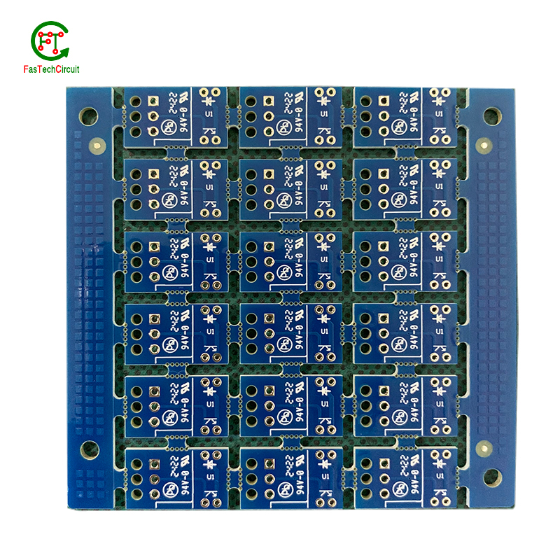
A PCB (Printed Circuit Board) is a flat board made of non-conductive material, such as fiberglass, with conductive pathways etched or printed onto it. The main purpose of a PCB is to provide a platform for electronic components to be mounted and connected together to form a functioning electronic circuit. It serves as a physical support for the components and provides a means for them to communicate with each other through the conductive pathways. PCBs are used in a wide range of electronic devices, from simple household appliances to complex computer systems, and are essential for the proper functioning and reliability of these devices. They also allow for easier and more efficient production of electronic devices, as the components can be mounted and connected in a standardized and automated manner.
4.How are cell phone jammer pcb layout used in medical devices?
Printed Circuit Boards (PCBs) are essential components used in a wide range of medical devices, playing a crucial role in both diagnostic and treatment equipment. These devices require reliable and precise circuitry to accurately collect and process data, deliver therapies, and regulate medical procedures. PCBs are used in equipment such as MRI machines, pacemakers, defibrillators, and monitors, where their small size and high density make them ideal for compact and portable designs. In addition, PCBs are also used in medical implants, enabling a safe and secure connection between the device and the body. With their advanced technology, PCBs continue to be an integral part of the medical industry, ensuring the effectiveness and success of various medical procedures and treatments.
5.What is the maximum operating temperature of a cell phone jammer pcb layout?
We have a professional team that is committed to the innovation and development of cell phone jammer pcb layout.
The maximum operating temperature of a PCB (printed circuit board) can vary depending on the materials and components used in its construction. Generally, the maximum operating temperature for a standard FR4 PCB is around 130-140 degrees Celsius. However, specialized materials such as high-temperature laminates or ceramic substrates can withstand higher temperatures up to 200-250 degrees Celsius. The maximum operating temperature of a PCB should always be determined by the manufacturer's specifications and guidelines.
6.What is the power rating for a cell phone jammer pcb layout?
We maintain a certain amount of R&D investment every year and continuously improve operational efficiency to provide better services to our cooperative customers.
The power rating for a PCB (printed circuit board) can vary greatly depending on its size, design, and intended use. Generally, the power rating for a PCB is determined by the maximum amount of current it can safely handle without overheating or causing damage. This can range from a few milliamps for small, low-power circuits to several amps for larger, high-power circuits. It is important to consult the manufacturer's specifications or consult with an engineer to determine the specific power rating for a particular PCB.
7.Can cell phone jammer pcb layouts be used for high-speed data transmission?
Yes, PCBs (printed circuit boards) can be used for high-speed data transmission. PCBs are commonly used in electronic devices and systems to connect and route electrical signals between components. They are designed to have specific trace widths, lengths, and impedance to ensure efficient and reliable transmission of high-speed signals. Additionally, PCBs can be designed with specialized materials and techniques, such as controlled impedance and differential signaling, to further optimize their performance for high-speed data transmission.
8.How are signal traces routed on a cell phone jammer pcb layout?
Signal traces are an essential element of a PCB, responsible for carrying electronic signals between components and ensuring proper communication and functionality of the circuit. To route these traces, designers use specialized software to determine the most efficient and optimal path for each signal, taking into account factors such as signal integrity, trace length, and potential interference. This process involves careful planning, as well as techniques such as vias, ground and power planes, and differential pairs to minimize noise and maintain signal integrity.
9.How are power and ground planes connected on a cell phone jammer pcb layout?
Power and ground planes are typically connected on a PCB through vias, which are small holes drilled through the layers of the PCB. These vias are filled with conductive material, such as copper, and allow for the flow of current between the power and ground planes. The vias are strategically placed throughout the PCB to ensure a low impedance connection between the power and ground planes. Additionally, traces or copper pours can also be used to connect the power and ground planes on different layers of the PCB.
10.What techniques are used for reducing electromagnetic interference (EMI) on a cell phone jammer pcb layout?
Electromagnetic interference (EMI) is a disturbance caused by electromagnetic radiation that can disrupt the proper functioning of electronic devices. To reduce EMI on a PCB, a number of techniques can be employed. One common technique is to use a ground plane, which acts as a shield to block electromagnetic waves from interfering with the circuit. Another approach is to use proper placement and routing of components and traces to minimize the length of signal paths and reduce the chances of signal crossover. Additionally, using components like capacitors and ferrite beads can help to filter out high-frequency noise. Careful consideration and design of the PCB layout is also crucial in reducing EMI, as the placement, size, and orientation of components can impact electromagnetic emissions. By employing these techniques, EMI on a PCB can be effectively reduced, leading to improved performance and reliability of electronic devices.
11.Can cell phone jammer pcb layouts be used in automotive applications?
Yes, PCBs (printed circuit boards) can be used in automotive applications. They are commonly used in various electronic systems in vehicles, such as engine control units, infotainment systems, and safety systems. PCBs offer a compact and reliable way to connect and control electronic components in vehicles. They are also designed to withstand harsh environmental conditions, such as temperature fluctuations, vibrations, and moisture, making them suitable for use in automotive applications.
12.What is the maximum size of a cell phone jammer pcb layout?
We pay attention to the introduction and training of talents, scientifically regulate the management system, and focus on cultural construction and team cohesion.
The maximum size of a PCB (printed circuit board) can vary depending on the manufacturer and theircapabilities. However, the industry standard maximum size for a single PCB panel is typically around 18 inches by 24 inches (457 mm by 610 mm). Larger PCBs can be created by combining multiple panels together. Some manufacturers may also have the capability to create custom-sized PCBs that exceed the industry standard maximum size.
13.What software is used for cell phone jammer pcb layout design?
Our cell phone jammer pcb layout products have competitive and differentiated advantages, and actively promote digital transformation and innovation.
Some popular software used for PCB design include:
1. Altium Designer
2. Eagle PCB
3. KiCad
4. OrCAD
5. PADS
6. Proteus
7. DipTrace
8. EasyEDA
9. CircuitMaker
10. DesignSpark PCB
14.How are high-frequency signals handled on a cell phone jammer pcb layout?
High-frequency signals are typically handled with great care and precision on a PCB to ensure optimal performance. This involves using high-quality materials, such as high-speed laminates and low-loss dielectrics, to minimize signal loss and interference. Additionally, designers must carefully consider the trace routing and placement of components on the PCB to minimize signal reflections and keep the signal path as short and direct as possible. Specialized techniques, like controlled impedance and shielding, may also be used to further improve signal integrity.
RELATED PRODUCTS & SERVICE
pcb board manufacturing How To Contact US
PCB from 1 to 30 layers, HDI, Heavy Copper, Rigid-flex board with "pcb board manufacturing One-Stop" service.

