120v ldr relay circuit pcb
As a professional PCB manufacturer, our product range includes single-sided boards, double-sided boards, multi-layer boards, rigid-flexible connection boards, high-frequency boards, blind through boards, buried via boards, etc. At the same time, we also provide a variety of surface treatment processes, such as HASL, ENIG, OSP, metal spraying, etc., to meet the different needs of customers. We can provide one-stop OEM service with price advantage and fast delivery!
Our products are widely used in consumer electronics, communication equipment, industrial control, automotive electronics and other fields, and enjoy a high reputation in domestic and foreign markets. Our team has rich PCB manufacturing experience and professional skills and can provide customers with customized products and solutions. At the same time, we are also committed to continuously launching competitive and innovative products to meet the changing needs of customers. All our products comply with international quality standards and our customers come from different markets around the world. For example $keyworRd{4} etc.
| Model Number | customized PCBA |
| Type | pcba |
| Place of Origin | Guangdong, China |
| Brand Name | none |
| Copper Thickness | 1 oz |
| Supplier Type | OEM |
| Application | Electronics Device |
| Service | One-step Service |
| Layer | 1-42layers |
| Solder mask color | Blue.green.red.black.white.etc |
| Testing Service | 100% |
| Component size | 0201-1173mm |
| Component max height | 24mm |
| Min lead pitch | 0.4mm |
| Min BGA ball pitch | 0.4mm |
| Max PCB size | 426x554mm |
| Packaging Details | Vacuum package for bare PCB and ESD package for PCBA Printed Circuit Board Factory FPC Board PCBA Companies PCBA Assembly |
| Supply Ability | 43215 Piece/Pieces per Week |
| Quantity (pieces) | > 716 |
| Lead time (days) | 9 |
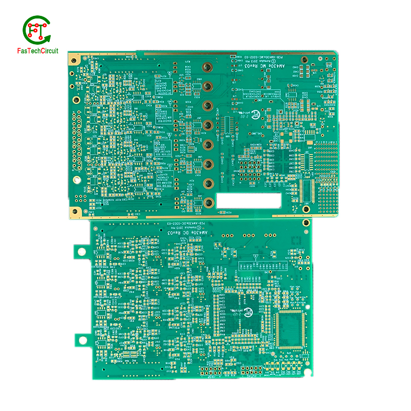
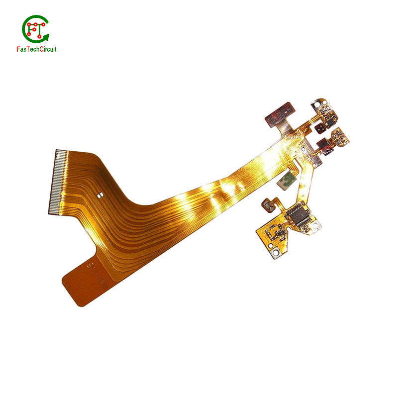
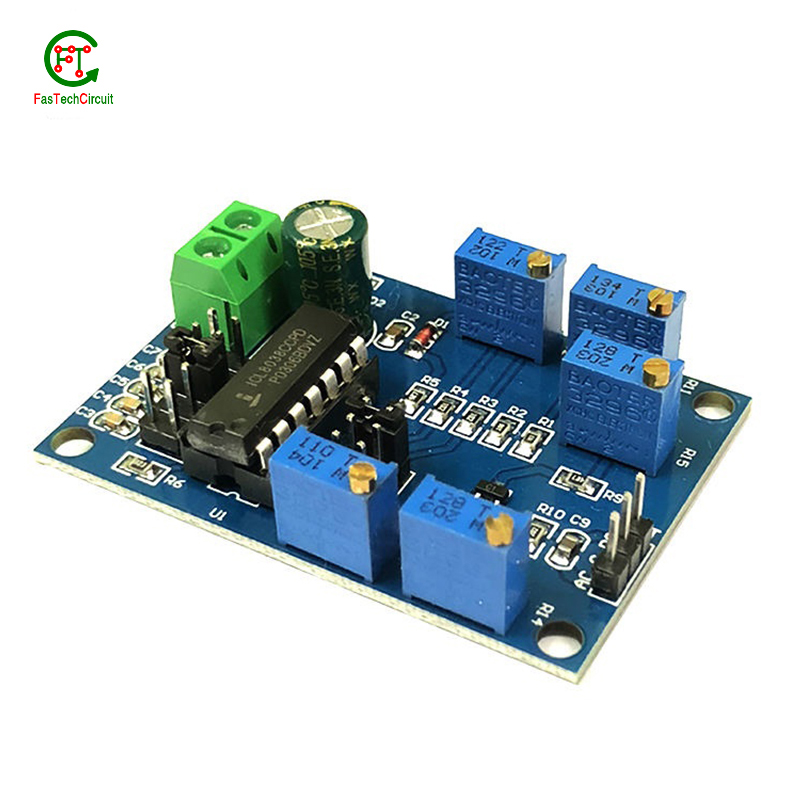
120v ldr relay circuit pcb bearings FAQs Guide Welcome to our state-of-the-art PCB (Printed Circuit Board) products. We are proud to offer a comprehensive range of high-quality and versatile PCB solutions to meet the constantly evolving needs of the modern electronics industry.Our PCBs are expertly designed and manufactured using the latest technology and advanced techniques, ensuring reliability, durability, and exceptional performance for a wide range of applications. We understand the importance of precision and attention to detail in the production of PCBs and we are committed to meeting stringent quality standards.
2.What is the standard thickness for copper used in 120v ldr relay circuit pcbs?
3.How are components attached to a 120v ldr relay circuit pcb?
4.What is the purpose of a solder mask on a 120v ldr relay circuit pcb?
5.What is the role of silkscreen on a 120v ldr relay circuit pcb?
6.What is the typical lifespan of a 120v ldr relay circuit pcb?
7.How are high-speed/high-frequency 120v ldr relay circuit pcb tested and validated?
8.What is the minimum size of a through-hole component that can be used on a 120v ldr relay circuit pcb?
9.What is the difference between an analog and a digital signal on a 120v ldr relay circuit pcb?
10.Can 120v ldr relay circuit pcbs be used for high-temperature applications?
11.What are the main components of a 120v ldr relay circuit pcb?
12.What is a 120v ldr relay circuit pcb?
13.How are signal traces routed on a 120v ldr relay circuit pcb?
14.What is the function of a decoupling capacitor on a 120v ldr relay circuit pcb?
15.What is the role of automated optical inspection (AOI) in 120v ldr relay circuit pcb production?
1.Can 120v ldr relay circuit pcbs be used for high-speed data transmission?
Yes, PCBs (printed circuit boards) can be used for high-speed data transmission. PCBs are commonly used in electronic devices and systems to connect and route electrical signals between components. They are designed to have specific trace widths, lengths, and impedance to ensure efficient and reliable transmission of high-speed signals. Additionally, PCBs can be designed with specialized materials and techniques, such as controlled impedance and differential signaling, to further optimize their performance for high-speed data transmission.
2.What is the standard thickness for copper used in 120v ldr relay circuit pcbs?
The standard thickness for copper used in PCBs is 1 ounce (oz) or 35 micrometers (µm). However, thicker copper layers such as 2 oz or 3 oz can also be used for higher current carrying capacity or better heat dissipation. The thickness of copper used in a PCB is determined by the design requirements and the intended use of the board.
3.How are components attached to a 120v ldr relay circuit pcb?
We adhere to the principle of integrity and transparency, and establish long -term relationships with partners, and we attach great importance to this detail.
eads or pins of the component and melting solder onto them, whicComponents are attached to a PCB (printed circuit board) through a process called soldering. This involves heating the metal lh then solidifies and creates a strong electrical and mechanical connection between the component and the PCB. There are two main methods of soldering components onto a PCB:
1. Through-hole soldering: This method involves inserting the leads or pins of the component through pre-drilled holes on the PCB and soldering them on the opposite side of the board. This method is commonly used for larger components such as resistors, capacitors, and integrated circuits.
2. Surface mount soldering: This method involves soldering the component directly onto the surface of the PCB, without the need for pre-drilled holes. This is done using specialized equipment such as a soldering iron or a reflow oven. Surface mount components are smaller in size and are commonly used for more complex and compact electronic devices.
4.What is the purpose of a solder mask on a 120v ldr relay circuit pcb?
We have a good reputation and image in the industry. The quality and price advantage of 120v ldr relay circuit pcb products is an important factor in our hard overseas market.
A solder mask is a thin layer of protective material applied to a printed circuit board (PCB) to prevent solder from bridging between conductive traces, pads, or vias during the soldering process. It also helps to protect the PCB from environmental factors such as moisture, dust, and corrosion. Additionally, the solder mask can provide insulation between conductive traces, reducing the risk of short circuits. It also helps to improve the overall appearance of the PCB by providing a uniform and professional finish.
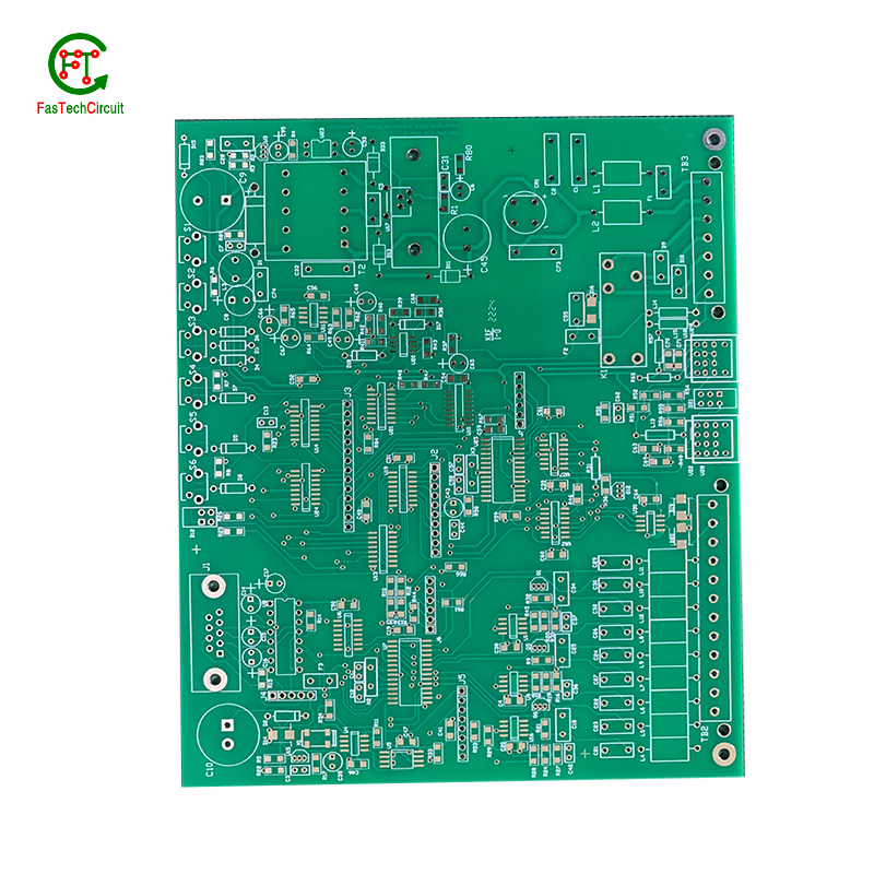
5.What is the role of silkscreen on a 120v ldr relay circuit pcb?
Being one of the top 120v ldr relay circuit pcb manufacturers in China, We attach great importance to this detail.
Silkscreen, also known as legend or nomenclature, is a vital component of a printed circuit board (PCB). It is the layer of text and symbols that are printed on the surface of the PCB to provide essential information for component placement and identification. The silkscreen plays a crucial role in the manufacturing process of PCBs, as it helps to ensure the accuracy and functionality of the final product. By indicating component locations, values, and reference designators, the silkscreen serves as a guide for the assembly and soldering of electronic components. Additionally, it also provides important information for maintenance and troubleshooting purposes.
6.What is the typical lifespan of a 120v ldr relay circuit pcb?
120v ldr relay circuit pcb is not a product only, but also can help you comes to money-making.
The typical lifespan of a PCB (printed circuit board) can vary greatly depending on various factors such as the quality of materials used, environmental conditions, and usage. In general, a well-designed and properly manufactured PCB can last for 10-20 years or more. However, some PCBs may fail prematurely due to factors such as corrosion, thermal stress, or mechanical damage. Regular maintenance and proper handling can also extend the lifespan of a PCB.
7.How are high-speed/high-frequency 120v ldr relay circuit pcb tested and validated?
Testing and validation are essential steps in the production process of high-speed and high-frequency printed circuit boards (PCBs). These specialized types of PCBs are used in a wide range of industries, including telecommunications, aerospace, and automotive, and require precision and reliability in their performance.
The testing and validation process for high-speed/high-frequency PCBs involves several steps to ensure that the final product meets the required specifications. This starts with design simulation and analysis using specialized software to verify the layout and electrical characteristics of the PCB.
Once the design is confirmed, prototype PCBs are manufactured and subjected to various tests, including signal integrity and power integrity tests. These tests evaluate the electrical performance of the PCB, such as its ability to transmit signals at high speeds and maintain signal integrity.
In addition to electrical tests, environmental and mechanical tests are also performed to assess the durability and reliability of the PCB under different conditions, such as temperature changes and mechanical stress.
The final step in the testing and validation process is the inspection and analysis of the tested PCBs. This involves a detailed review of the test results and any necessary modifications to meet the required specifications.
8.What is the minimum size of a through-hole component that can be used on a 120v ldr relay circuit pcb?
We continue to invest in research and development and continue to launch innovative products.
The minimum size of a through-hole component that can be used on a PCB depends on the capabilities of the PCB manufacturer and the design requirements of the circuit. Generally, the minimum size for a through-hole component is around 0.2mm in diameter, but some manufacturers may be able to produce smaller sizes. It is important to consult with the manufacturer and consider the design requirements to determine the appropriate size for a through-hole component on a PCB.
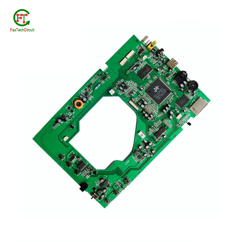
9.What is the difference between an analog and a digital signal on a 120v ldr relay circuit pcb?
An analog signal is a continuous signal that varies in amplitude and frequency over time. It can take on any value within a given range and is typically represented by a smooth, continuous waveform. Analog signals are used to transmit information such as audio, video, and sensor data.
A digital signal, on the other hand, is a discrete signal that can only take on a limited number of values. It is represented by a series of binary digits (0s and 1s) and can only have two states: on or off. Digital signals are used to transmit information in the form of data and are commonly used in digital electronics such as computers and smartphones.
On a PCB, the main difference between analog and digital signals lies in the way they are processed and transmitted. Analog signals require specialized components such as amplifiers and filters to maintain their integrity, while digital signals can be processed and transmitted using digital logic circuits. Additionally, analog signals are more susceptible to noise and interference, while digital signals are more immune to these factors.
10.Can 120v ldr relay circuit pcbs be used for high-temperature applications?
Yes, PCBs (printed circuit boards) can be used for high-temperature applications. However, the materials and design of the PCB must be carefully chosen to ensure that it can withstand the high temperatures without degrading or malfunctioning.
Some factors to consider when using PCBs for high-temperature applications include the type of substrate material, the type of solder used, and the thickness of the copper traces. High-temperature substrates such as ceramic or polyimide can withstand temperatures up to 300°C, while standard FR4 substrates are only suitable for temperatures up to 130°C.
Specialized solder materials, such as high-temperature lead-free solders, may also be necessary to ensure the reliability of the PCB at high temperatures. Additionally, thicker copper traces can help dissipate heat more effectively and prevent damage to the PCB.
11.What are the main components of a 120v ldr relay circuit pcb?
We continuously upgrade our skills and knowledge to adapt to changing 120v ldr relay circuit pcb market needs.
A typical PCB consists of several vital components, including a substrate material, copper traces, solder mask, silk screen, and plated through-holes. The substrate material acts as the base and provides mechanical support for the board. Copper traces, usually made of thin lines of copper foil, serve as the conductive paths for transmitting electrical signals. The solder mask, applied as a protective layer, prevents accidental short circuits and corrosion. Silk screen, a layer of ink-based labeling, aids in component identification. Lastly, plated through-holes enable electrical connection between different layers of the PCB board. These components work together to form a fully functioning PCB.
12.What is a 120v ldr relay circuit pcb?
We pay attention to user experience and product quality, and provide the best product quality and lowest production cost for cooperative customers.
A PCB (Printed Circuit Board) is a flat board made of non-conductive material, such as fiberglass, with conductive pathways etched or printed onto it. It is used to mechanically support and electrically connect electronic components using conductive tracks, pads, and other features etched from copper sheets laminated onto a non-conductive substrate. PCBs are commonly used in electronic devices such as computers, smartphones, and televisions to provide a platform for the components to be mounted and connected together. They are also used in a variety of other applications, including automotive, aerospace, and medical devices.
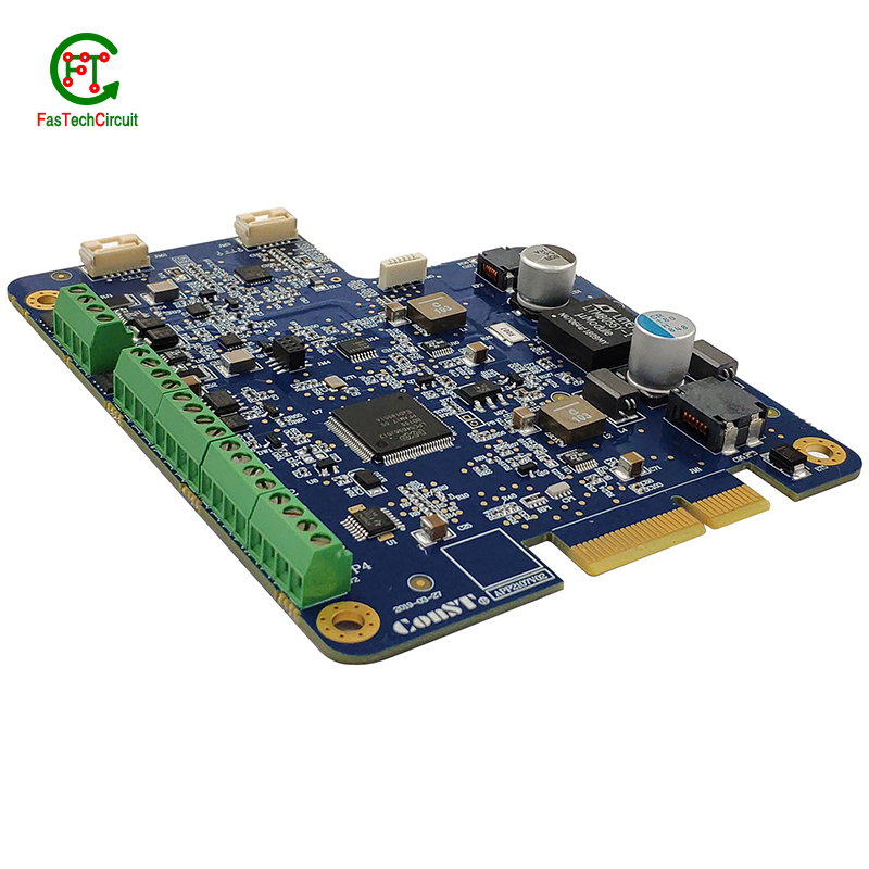
13.How are signal traces routed on a 120v ldr relay circuit pcb?
Signal traces are an essential element of a PCB, responsible for carrying electronic signals between components and ensuring proper communication and functionality of the circuit. To route these traces, designers use specialized software to determine the most efficient and optimal path for each signal, taking into account factors such as signal integrity, trace length, and potential interference. This process involves careful planning, as well as techniques such as vias, ground and power planes, and differential pairs to minimize noise and maintain signal integrity.
14.What is the function of a decoupling capacitor on a 120v ldr relay circuit pcb?
We have rich industry experience and professional knowledge, and have strong competitiveness in the market.
A decoupling capacitor is a type of capacitor that is used to reduce or eliminate noise and interference in electronic circuits. It is typically placed on a PCB (printed circuit board) near the power supply pins of an integrated circuit (IC) or other active component.
The main function of a decoupling capacitor is to provide a stable and clean power supply to the IC or other active component. This is achieved by filtering out high-frequency noise and voltage fluctuations that can be caused by other components on the PCB or external sources.
In addition, a decoupling capacitor also helps to prevent voltage drops and spikes that can occur when the IC or other component suddenly draws a large amount of current. This is especially important for sensitive components that require a stable power supply to function properly.
15.What is the role of automated optical inspection (AOI) in 120v ldr relay circuit pcb production?
Automated optical inspection (AOI) plays a crucial role in the production of printed circuit boards (PCBs). It is a technology that uses advanced imaging techniques to detect and identify defects or errors on a PCB, such as missing components, incorrect placement, and faulty soldering. AOI has become an essential step in the production process as it helps manufacturers ensure the quality and reliability of their PCBs. By detecting and identifying defects at an early stage, AOI can significantly reduce the number of defects and increase the efficiency of the production process. Furthermore, AOI is able to perform inspections at a much faster rate and with higher accuracy compared to manual inspection, making it an indispensable tool for PCB production.
RELATED PRODUCTS & SERVICE
pcb board manufacturing How To Contact US
PCB from 1 to 30 layers, HDI, Heavy Copper, Rigid-flex board with "pcb board manufacturing One-Stop" service.

