94 v0 pcb board
In view of meeting the different quantity requirements of our customers, we have planned to expand our factory to meet all small to large orders and prototype additional requirements without MOQ (Minimum Order Quantity). We have won high praise from customers from Europe, America, Asia, Cayman Islands,Sudan,Paracel Islands,Vanuatu,Netherlands,Uganda... and so on.
| Model Number | customized PCBA |
| Type | pcba |
| Place of Origin | Guangdong, China |
| Brand Name | none |
| Copper Thickness | 1 oz |
| Supplier Type | OEM |
| Application | Electronics Device |
| Service | One-step Service |
| Layer | 1-41layers |
| Solder mask color | Blue.green.red.black.white.etc |
| Testing Service | 100% |
| Component size | 0201-1154mm |
| Component max height | 28mm |
| Min lead pitch | 0.2mm |
| Min BGA ball pitch | 0.2mm |
| Max PCB size | 560x373mm |
| Packaging Details | Vacuum package for bare PCB and ESD package for PCBA Printed Circuit Board Factory FPC Board PCBA Companies PCBA Assembly |
| Supply Ability | 52663 Piece/Pieces per Week |
| Quantity (pieces) | > 885 |
| Lead time (days) | 11 |
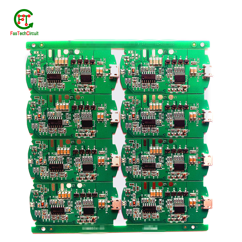
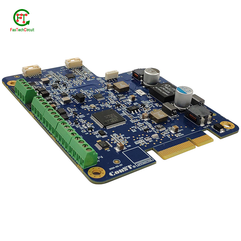
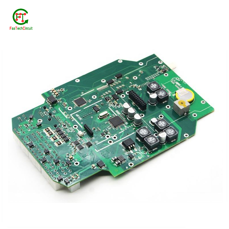
94 v0 pcb board bearings FAQs Guide Welcome to our state-of-the-art PCB (Printed Circuit Board) products. We are proud to offer a comprehensive range of high-quality and versatile PCB solutions to meet the constantly evolving needs of the modern electronics industry.Our PCBs are expertly designed and manufactured using the latest technology and advanced techniques, ensuring reliability, durability, and exceptional performance for a wide range of applications. We understand the importance of precision and attention to detail in the production of PCBs and we are committed to meeting stringent quality standards.
2.How are power and ground planes connected on a 94 v0 pcb board?
3.Can a 94 v0 pcb board be repaired if damaged?
4.What is the role of silkscreen on a 94 v0 pcb board?
5.What type of material is used for the silkscreen on a 94 v0 pcb board?
6.What is the standard thickness for copper used in 94 v0 pcb boards?
7.What is the role of a data sheet in 94 v0 pcb board design?
8.How is a 94 v0 pcb board tested for functionality?
9.What is the difference between an analog and a digital signal on a 94 v0 pcb board?
10.Can 94 v0 pcb boards be used in high voltage applications?
11.How are signal traces routed on a 94 v0 pcb board?
12.What is the difference between single-sided, double-sided, and multi-layer 94 v0 pcb board?
13.What are the most common uses for 94 v0 pcb board?
14.What is the purpose of a ground plane on a 94 v0 pcb board?
15.What is a through-hole component?
16.What type of solder is used for 94 v0 pcb board assembly?
17.How are 94 v0 pcb boards designed?
1.What is the function of a decoupling capacitor on a 94 v0 pcb board?
We have rich industry experience and professional knowledge, and have strong competitiveness in the market.
A decoupling capacitor is a type of capacitor that is used to reduce or eliminate noise and interference in electronic circuits. It is typically placed on a PCB (printed circuit board) near the power supply pins of an integrated circuit (IC) or other active component.
The main function of a decoupling capacitor is to provide a stable and clean power supply to the IC or other active component. This is achieved by filtering out high-frequency noise and voltage fluctuations that can be caused by other components on the PCB or external sources.
In addition, a decoupling capacitor also helps to prevent voltage drops and spikes that can occur when the IC or other component suddenly draws a large amount of current. This is especially important for sensitive components that require a stable power supply to function properly.
2.How are power and ground planes connected on a 94 v0 pcb board?
Power and ground planes are typically connected on a PCB through vias, which are small holes drilled through the layers of the PCB. These vias are filled with conductive material, such as copper, and allow for the flow of current between the power and ground planes. The vias are strategically placed throughout the PCB to ensure a low impedance connection between the power and ground planes. Additionally, traces or copper pours can also be used to connect the power and ground planes on different layers of the PCB.
3.Can a 94 v0 pcb board be repaired if damaged?
We focus on teamwork and communication to achieve common goals, We attach great importance to this detail.
Yes, a PCB (printed circuit board) can be repaired if it is damaged. The extent of the damage and the complexity of the circuit will determine the difficulty and feasibility of the repair. Some common methods for repairing a damaged PCB include:
1. Soldering: If the damage is limited to a few components or traces, they can be replaced or repaired by soldering new components or wires onto the board.
2. Trace repair: If a trace (conductive pathway) on the PCB is damaged or broken, it can be repaired by using a conductive ink or wire to bridge the gap.
3. Component replacement: If a specific component on the PCB is damaged, it can be replaced with a new one. This requires identifying the damaged component and sourcing a replacement.
4. PCB rework: In some cases, the entire PCB may need to be reworked, which involves removing and replacing multiple components and traces.
4.What is the role of silkscreen on a 94 v0 pcb board?
Being one of the top 94 v0 pcb board manufacturers in China, We attach great importance to this detail.
Silkscreen, also known as legend or nomenclature, is a vital component of a printed circuit board (PCB). It is the layer of text and symbols that are printed on the surface of the PCB to provide essential information for component placement and identification. The silkscreen plays a crucial role in the manufacturing process of PCBs, as it helps to ensure the accuracy and functionality of the final product. By indicating component locations, values, and reference designators, the silkscreen serves as a guide for the assembly and soldering of electronic components. Additionally, it also provides important information for maintenance and troubleshooting purposes.
5.What type of material is used for the silkscreen on a 94 v0 pcb board?
We have a wide range of 94 v0 pcb board customer groups and establishes long -term cooperative relationships with partners. The countries we provide services include .
The material used for the silkscreen on a PCB is typically a white or black ink made of epoxy or acrylic. It is applied using a screen printing process and is cured at high temperatures to ensure durability and resistance to chemicals and solvents.
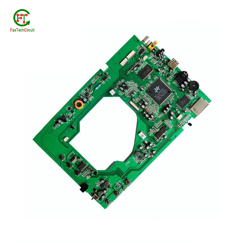
6.What is the standard thickness for copper used in 94 v0 pcb boards?
The standard thickness for copper used in PCBs is 1 ounce (oz) or 35 micrometers (µm). However, thicker copper layers such as 2 oz or 3 oz can also be used for higher current carrying capacity or better heat dissipation. The thickness of copper used in a PCB is determined by the design requirements and the intended use of the board.
7.What is the role of a data sheet in 94 v0 pcb board design?
A data sheet is an essential tool for PCB design, providing vital information and specifications for all of the components used in the design process. It contains detailed technical data, such as dimensions, electrical ratings, and performance characteristics, that allow designers to make informed decisions when selecting and placing components on a PCB. By referencing the data sheet, designers can ensure that each component is properly integrated into the overall design, following any necessary guidelines or restrictions. Additionally, data sheets also provide necessary information for the layout and routing of traces on the PCB, ensuring that the design can meet required performance specifications.
8.How is a 94 v0 pcb board tested for functionality?
A PCB, or Printed Circuit Board, is tested for functionality to ensure that all components and connections on the board are working correctly. This is important in order to detect any potential manufacturing or design defects that could compromise the board's performance. To test a PCB, a range of diagnostic tools and techniques are used including visual inspection, automated testing software, and specialized equipment such as oscilloscopes and multimeters. Experienced technicians also use their knowledge and expertise to troubleshoot and identify any issues with the board. Through this rigorous testing process, any faults or failures are identified and resolved before the PCB is released for production, ensuring that it meets the desired functionality and performance standards.
9.What is the difference between an analog and a digital signal on a 94 v0 pcb board?
An analog signal is a continuous signal that varies in amplitude and frequency over time. It can take on any value within a given range and is typically represented by a smooth, continuous waveform. Analog signals are used to transmit information such as audio, video, and sensor data.
A digital signal, on the other hand, is a discrete signal that can only take on a limited number of values. It is represented by a series of binary digits (0s and 1s) and can only have two states: on or off. Digital signals are used to transmit information in the form of data and are commonly used in digital electronics such as computers and smartphones.
On a PCB, the main difference between analog and digital signals lies in the way they are processed and transmitted. Analog signals require specialized components such as amplifiers and filters to maintain their integrity, while digital signals can be processed and transmitted using digital logic circuits. Additionally, analog signals are more susceptible to noise and interference, while digital signals are more immune to these factors.
10.Can 94 v0 pcb boards be used in high voltage applications?
We have advantages in marketing and channel expansion. Suppliers have established good cooperative relations, continuously improved workflows, improved efficiency and productivity, and provided customers with high -quality products and services.
Yes, PCBs (printed circuit boards) can be used in high voltage applications. However, the design and construction of the PCB must be carefully considered to ensure it can withstand the high voltage without causing damage or malfunction. This may include using specialized materials, increasing the spacing between components, and implementing proper insulation and grounding techniques. It is important to consult with a qualified engineer or designer when using PCBs in high voltage applications to ensure safety and reliability.
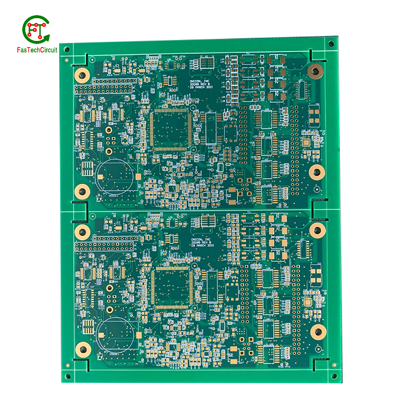
11.How are signal traces routed on a 94 v0 pcb board?
Signal traces are an essential element of a PCB, responsible for carrying electronic signals between components and ensuring proper communication and functionality of the circuit. To route these traces, designers use specialized software to determine the most efficient and optimal path for each signal, taking into account factors such as signal integrity, trace length, and potential interference. This process involves careful planning, as well as techniques such as vias, ground and power planes, and differential pairs to minimize noise and maintain signal integrity.
12.What is the difference between single-sided, double-sided, and multi-layer 94 v0 pcb board?
We have established a good reputation and reliable partnerships within the 94 v0 pcb board industry.
Single-sided PCB (Printed Circuit Board) is a type of PCB that has components and traces on only one side of the board. The other side is usually used for soldering and mounting the board onto a larger circuit.
Double-sided PCB is a type of PCB that has components and traces on both sides of the board. The traces on both sides are connected through vias, which are small holes drilled through the board and plated with metal to create an electrical connection.
Multi-layer PCB is a type of PCB that has multiple layers of conductive material and insulating material sandwiched together. The layers are connected through vias, allowing for more complex and compact circuit designs. Multi-layer PCBs are used in more advanced and high-performance electronic devices.
13.What are the most common uses for 94 v0 pcb board?
We enjoy high authority and influence in the industry and continue to innovate products and service models.
Printed circuit boards, or PCBs, are widely used in electronic devices and equipment. They are used in everything from smartphones and computers to household appliances and automotive systems. PCBs are essential components for connecting electrical and electronic components together, providing a robust and reliable platform for digital and analog signals to pass through. Common uses for PCBs include controlling and powering electronic devices, storing and processing data, and providing a means of communication between components. They are also used in various industrial and commercial applications, such as automation and control systems, medical equipment, and aerospace technology. PCBs offer a cost-effective and efficient solution for creating complex electronic circuits, making them a crucial component in modern technology.
14.What is the purpose of a ground plane on a 94 v0 pcb board?
I have a comprehensive after -sales service system, which can pay attention to market trends in time and adjust our strategy in a timely manner.
A decoupling capacitor is an essential component on a PCB (Printed Circuit Board) which is used to reduce or eliminate high frequency noise between different components. It acts as a buffer between the power supply and other circuit components, by storing electrical charge and then releasing it when there is a sudden change in the supply voltage. This helps to stabilize the power supply, providing a steady and noise-free flow of electricity to the circuit. Furthermore, decoupling capacitors also help to filter out any unwanted signals that may cause interference or disruptions in the proper functioning of the circuit.
15.What is a through-hole component?
We focus on providing high 94 v0 pcb board quality products and services.
A through-hole component is an electronic component that has leads or pins that are inserted into holes on a printed circuit board (PCB) and then soldered to the opposite side of the board. This type of component is typically larger and more robust than surface mount components, and is often used for high-power or high-voltage applications. Through-hole components are also easier to replace or repair compared to surface mount components.
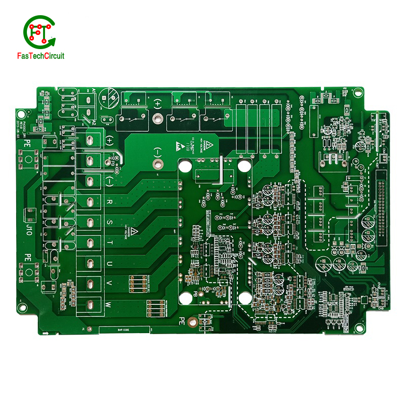
16.What type of solder is used for 94 v0 pcb board assembly?
The most commonly used solder for PCB assembly is a lead-free solder, specifically a tin-silver-copper (SnAgCu) alloy. This type of solder is preferred due to its high melting point, good wetting properties, and compatibility with surface mount technology (SMT) components. Other types of solder that may be used include tin-lead (SnPb) solder and lead-free alternatives such as tin-copper (SnCu) and tin-bismuth (SnBi) alloys. The specific type of solder used may vary depending on the application and industry standards.
17.How are 94 v0 pcb boards designed?
We should perform well in market competition, and the prices of 94 v0 pcb board products have a great competitive advantage.
Printed Circuit Boards, commonly known as PCBs, are an essential part of modern-day technology. They serve as the foundation for electronic devices and are crucial to their functionality. The process of designing a PCB involves several stages, starting with creating a schematic diagram that outlines the connections between various electronic components. This is followed by placement and routing, where the physical layout of the board is determined and traces are added to connect the components. PCB designers use advanced software to optimize the layout and ensure that it meets the necessary electrical and mechanical requirements. Once the design is finalized, manufacturers can use the design files to produce the PCB. Designing a PCB requires a combination of technical knowledge, creativity, and attention to detail to create a functional and efficient circuit board for a specific application.
RELATED PRODUCTS & SERVICE
pcb board manufacturing How To Contact US
PCB from 1 to 30 layers, HDI, Heavy Copper, Rigid-flex board with "pcb board manufacturing One-Stop" service.

