1117 pcb layout
| Model Number | customized PCBA |
| Type | pcba |
| Place of Origin | Guangdong, China |
| Brand Name | none |
| Copper Thickness | 1 oz |
| Supplier Type | OEM |
| Application | Electronics Device |
| Service | One-step Service |
| Layer | 1-36layers |
| Solder mask color | Blue.green.red.black.white.etc |
| Testing Service | 100% |
| Component size | 0201-1105mm |
| Component max height | 18mm |
| Min lead pitch | 0.4mm |
| Min BGA ball pitch | 0.5mm |
| Max PCB size | 479x424mm |
| Packaging Details | Vacuum package for bare PCB and ESD package for PCBA Printed Circuit Board Factory FPC Board PCBA Companies PCBA Assembly |
| Supply Ability | 49476 Piece/Pieces per Week |
| Quantity (pieces) | > 844 |
| Lead time (days) | 9 |
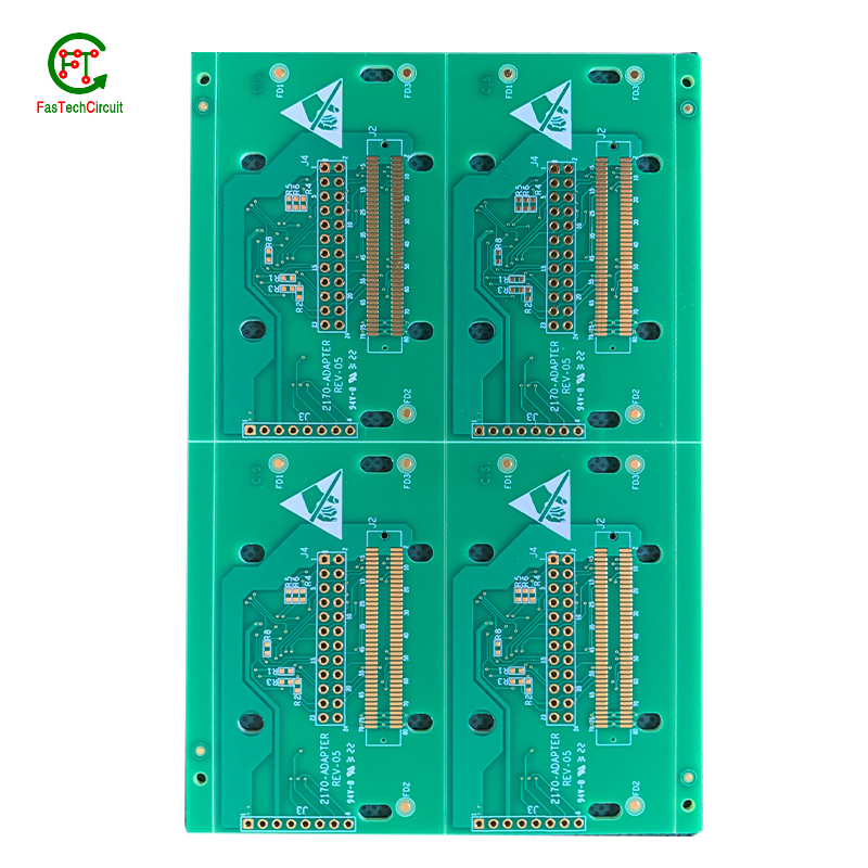
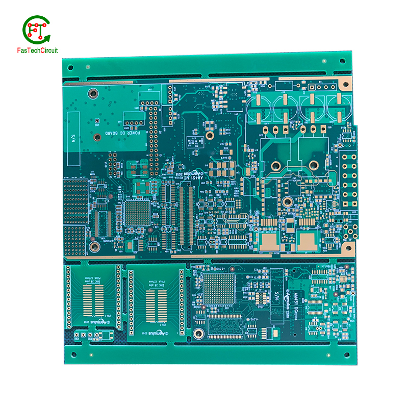
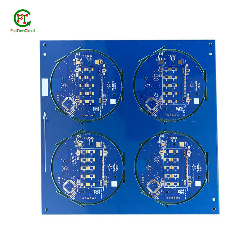
1117 pcb layout bearings FAQs Guide Welcome to our state-of-the-art PCB (Printed Circuit Board) products. We are proud to offer a comprehensive range of high-quality and versatile PCB solutions to meet the constantly evolving needs of the modern electronics industry.Our PCBs are expertly designed and manufactured using the latest technology and advanced techniques, ensuring reliability, durability, and exceptional performance for a wide range of applications. We understand the importance of precision and attention to detail in the production of PCBs and we are committed to meeting stringent quality standards.
2.How are 1117 pcb layouts designed?
3.How are signal traces routed on a 1117 pcb layout?
4.What is the role of vias on a 1117 pcb layout?
5.Are 1117 pcb layout recyclable?
6.What is the minimum size of a through-hole component that can be used on a 1117 pcb layout?
7.What are some common problems that can occur with 1117 pcb layout?
8.Can 1117 pcb layouts be used for high-speed data transmission?
9.How does a 1117 pcb layout work?
10.What is the purpose of a solder mask on a 1117 pcb layout?
11.What is the future outlook for 1117 pcb layout technology?
12.What is the function of a decoupling capacitor on a 1117 pcb layout?
13.Can 1117 pcb layouts be used in high voltage applications?
1.What are the main components of a 1117 pcb layout?
We continuously upgrade our skills and knowledge to adapt to changing 1117 pcb layout market needs.
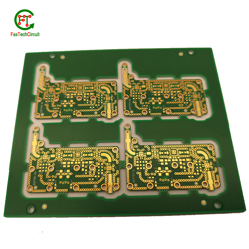
A typical PCB consists of several vital components, including a substrate material, copper traces, solder mask, silk screen, and plated through-holes. The substrate material acts as the base and provides mechanical support for the board. Copper traces, usually made of thin lines of copper foil, serve as the conductive paths for transmitting electrical signals. The solder mask, applied as a protective layer, prevents accidental short circuits and corrosion. Silk screen, a layer of ink-based labeling, aids in component identification. Lastly, plated through-holes enable electrical connection between different layers of the PCB board. These components work together to form a fully functioning PCB.
2.How are 1117 pcb layouts designed?
We should perform well in market competition, and the prices of 1117 pcb layout products have a great competitive advantage.
Printed Circuit Boards, commonly known as PCBs, are an essential part of modern-day technology. They serve as the foundation for electronic devices and are crucial to their functionality. The process of designing a PCB involves several stages, starting with creating a schematic diagram that outlines the connections between various electronic components. This is followed by placement and routing, where the physical layout of the board is determined and traces are added to connect the components. PCB designers use advanced software to optimize the layout and ensure that it meets the necessary electrical and mechanical requirements. Once the design is finalized, manufacturers can use the design files to produce the PCB. Designing a PCB requires a combination of technical knowledge, creativity, and attention to detail to create a functional and efficient circuit board for a specific application.
3.How are signal traces routed on a 1117 pcb layout?
Signal traces are an essential element of a PCB, responsible for carrying electronic signals between components and ensuring proper communication and functionality of the circuit. To route these traces, designers use specialized software to determine the most efficient and optimal path for each signal, taking into account factors such as signal integrity, trace length, and potential interference. This process involves careful planning, as well as techniques such as vias, ground and power planes, and differential pairs to minimize noise and maintain signal integrity.
4.What is the role of vias on a 1117 pcb layout?
Our company has many years of 1117 pcb layout experience and expertise.
Vias play a crucial role in connecting different layers of a printed circuit board (PCB). These small, plated holes act as conductive paths, allowing signals and power to pass through the board and reach various components. Vias are also essential for routing traces from one layer to another, optimizing the layout and reducing the size and complexity of the board. Additionally, vias provide structural support and improve thermal management by facilitating heat dissipation.
5.Are 1117 pcb layout recyclable?
We have been working hard to improve service quality and meet customer needs.
Yes, PCBs (printed circuit boards) are recyclable. They can be broken down and the individual components can be reused or repurposed. However, the recycling process can be complex and requires specialized equipment and techniques. It is important to properly dispose of PCBs to prevent environmental contamination and health hazards.
6.What is the minimum size of a through-hole component that can be used on a 1117 pcb layout?
We continue to invest in research and development and continue to launch innovative products.
The minimum size of a through-hole component that can be used on a PCB depends on the capabilities of the PCB manufacturer and the design requirements of the circuit. Generally, the minimum size for a through-hole component is around 0.2mm in diameter, but some manufacturers may be able to produce smaller sizes. It is important to consult with the manufacturer and consider the design requirements to determine the appropriate size for a through-hole component on a PCB.
7.What are some common problems that can occur with 1117 pcb layout?
Our 1117 pcb layout products undergo strict quality control to ensure customer satisfaction.
PCB (printed circuit boards) are an integral part of electronic devices, serving as the foundation for electrical connections and components. However, like any other technology, there are certain issues that may arise with PCB. One common problem is damage to the board due to excessive heat, as electronic components generate heat and if the PCB is not properly designed or ventilated, it can lead to malfunctions or even permanent damage. Another issue is poor soldering, which can result in weak connections or no connection at all. This can be caused by inadequate equipment or inexperience in the assembly process. Additionally, PCB can also suffer from corrosion over time, especially in high humidity environments, affecting its performance and reliability. It is important to address these problems early on to prevent further damage and ensure the functionality of electronic devices. Regular maintenance, proper design and assembly techniques, and use of quality materials can help prevent these common issues with PCB.
8.Can 1117 pcb layouts be used for high-speed data transmission?
Yes, PCBs (printed circuit boards) can be used for high-speed data transmission. PCBs are commonly used in electronic devices and systems to connect and route electrical signals between components. They are designed to have specific trace widths, lengths, and impedance to ensure efficient and reliable transmission of high-speed signals. Additionally, PCBs can be designed with specialized materials and techniques, such as controlled impedance and differential signaling, to further optimize their performance for high-speed data transmission.
9.How does a 1117 pcb layout work?
We maintain a stable growth through reasonable capital operations, focus on industry development trends and cutting -edge technologies, and focus on product quality and safety performance.
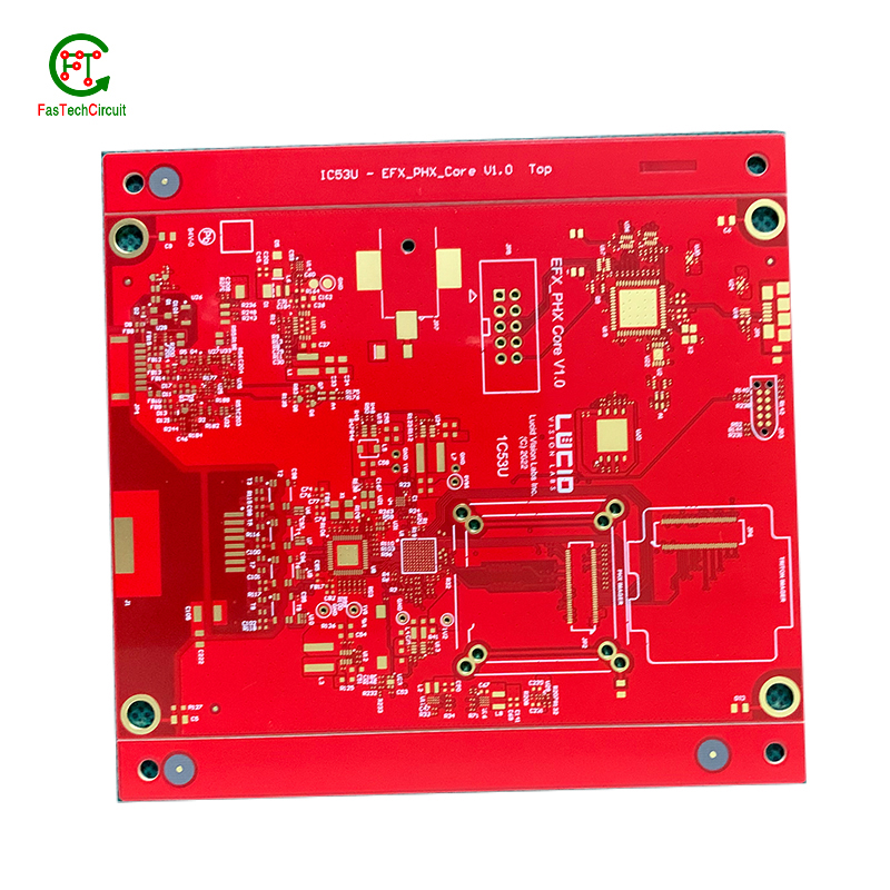
A PCB (Printed Circuit Board) is a thin board made of non-conductive material, such as fiberglass or plastic, with conductive pathways etched or printed onto its surface. These pathways, also known as traces, are used to connect electronic components on the board, such as resistors, capacitors, and integrated circuits.
The PCB works by providing a platform for the components to be mounted and connected in a specific circuit configuration. The traces on the board act as wires, allowing electricity to flow between the components and creating a complete circuit.
The process of creating a PCB involves several steps, including designing the circuit layout, printing or etching the traces onto the board, and attaching the components using soldering techniques. Once the components are attached, the board is tested to ensure that all connections are correct and functioning properly.
When a PCB is connected to a power source, electricity flows through the traces, powering the components and allowing them to perform their intended functions. The traces also act as a pathway for signals to travel between components, allowing for communication and data transfer within the circuit.
PCBs are used in a wide range of electronic devices, from simple household appliances to complex computer systems. They provide a compact and efficient way to connect and control electronic components, making them an essential part of modern technology.
10.What is the purpose of a solder mask on a 1117 pcb layout?
We have a good reputation and image in the industry. The quality and price advantage of 1117 pcb layout products is an important factor in our hard overseas market.
A solder mask is a thin layer of protective material applied to a printed circuit board (PCB) to prevent solder from bridging between conductive traces, pads, or vias during the soldering process. It also helps to protect the PCB from environmental factors such as moisture, dust, and corrosion. Additionally, the solder mask can provide insulation between conductive traces, reducing the risk of short circuits. It also helps to improve the overall appearance of the PCB by providing a uniform and professional finish.
11.What is the future outlook for 1117 pcb layout technology?
Printed Circuit Boards, or PCBs, have been a vital component in electronic devices for decades. They serve as the foundation for the electrical connections and components that make our devices function properly. As technology continues to advance, so does the demand for smaller, faster, and more efficient PCBs. With the rise of IoT and smart devices, the future outlook for PCB technology is promising. It is expected that PCBs will become even more compact and complex, utilizing advanced materials and techniques such as 3D printing and flexible substrates. This will not only improve the performance of electronic devices, but also make them more durable and cost-effective. Furthermore, as sustainability becomes a growing concern, eco-friendly PCB materials and manufacturing processes are being developed to reduce environmental impact. With these advancements, it is safe to say that the future of PCB technology is bright and full of endless possibilities.
12.What is the function of a decoupling capacitor on a 1117 pcb layout?
We have rich industry experience and professional knowledge, and have strong competitiveness in the market.
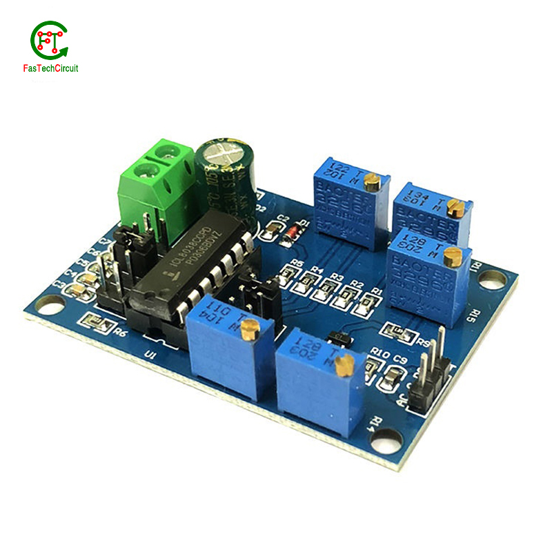
A decoupling capacitor is a type of capacitor that is used to reduce or eliminate noise and interference in electronic circuits. It is typically placed on a PCB (printed circuit board) near the power supply pins of an integrated circuit (IC) or other active component.
The main function of a decoupling capacitor is to provide a stable and clean power supply to the IC or other active component. This is achieved by filtering out high-frequency noise and voltage fluctuations that can be caused by other components on the PCB or external sources.
In addition, a decoupling capacitor also helps to prevent voltage drops and spikes that can occur when the IC or other component suddenly draws a large amount of current. This is especially important for sensitive components that require a stable power supply to function properly.
13.Can 1117 pcb layouts be used in high voltage applications?
We have advantages in marketing and channel expansion. Suppliers have established good cooperative relations, continuously improved workflows, improved efficiency and productivity, and provided customers with high -quality products and services.
Yes, PCBs (printed circuit boards) can be used in high voltage applications. However, the design and construction of the PCB must be carefully considered to ensure it can withstand the high voltage without causing damage or malfunction. This may include using specialized materials, increasing the spacing between components, and implementing proper insulation and grounding techniques. It is important to consult with a qualified engineer or designer when using PCBs in high voltage applications to ensure safety and reliability.
RELATED PRODUCTS & SERVICE
pcb board manufacturing How To Contact US
PCB from 1 to 30 layers, HDI, Heavy Copper, Rigid-flex board with "pcb board manufacturing One-Stop" service.

