2-layer pcb design rules
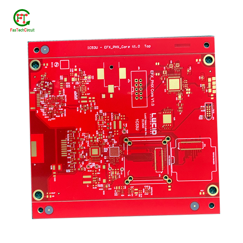
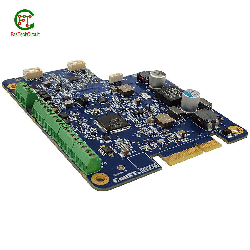
FasTechCircuit's products cover single-panel, double-panel, multi-layer boards, rigid boards, flexible boards, hybrid (rigid-soft) boards and other types. According to customer needs and application fields, we can provide PCB products of different materials and processes, such as FR-4, aluminum substrates, ceramic substrates, etc. At the same time, we can also provide a variety of surface treatment processes according to customer needs, such as OSP, HASL, ENIG, etc., to ensure the reliability and stability of the circuit board. We also provide non-standard customization services and can customize production according to the special requirements provided by customers to meet their personalized needs.
FasTechCircuit's printed circuit board products are widely used in communication equipment, industrial control, consumer electronics, computers and peripheral equipment, medical equipment, aerospace and other fields. Our products undergo strict quality control, have high precision, high reliability and stability, and can meet customers' high requirements for electronic products. Our products are very popular in Mozambique,Rwanda,Svalbard, the United States and Japan. Won high praise from customers.
| Base Material | FR-4/CEM-1/CEM-3/Polyimild/PTFE/Rogers |
| Board Thickness | 0.2-6mm |
| Model Number | Custom PCB & PCB Assembly |
| Type | Aluminum PCB |
| Brand Name | FC |
| Copper Thickness | 0.5-2mil(7-46um) |
| Min. Hole Size | 0.1mm(4mil)for HDI / 0.15mm(6mil) |
| Min. Line Width | 0.075mm/0.075mm(3mil/3mil) |
| Min. Line Spacing | 0.003'' |
| Surface Finishing | HASL/OSP/Ag/ENIG/ENEPIG/Immersion silver/Tin |
| Board Size | Custom |
| Model Number | Customized |
| Base Material | FR4 Aluminum CEM-1 94V0 |
| Surface Finishing | HASLENIG OSP |
| Number of layer | 1-15layer |
| Other service | Components purchasing and assem |
| ly Solder mask | White Black Green Blue,Red,etc. |
| Dsign service | Available |
| Testing | Function testing |
| Certificate | RoHS, ISO/TS16949, ISO9001 |
| Name | High Quality led light aluminum pcb printed circuit board |
| Packaging Details | Vaccum package and standard carton outside High Quality led light aluminum pcb printed circuit board |
| Supply Ability | 55925 Square Meter/Square Meters per Month |
| Quantity (pieces) | > 23036 |
| Lead time (days) | 5 |
2-layer pcb design rules bearings FAQs Guide Welcome to our state-of-the-art PCB (Printed Circuit Board) products. We are proud to offer a comprehensive range of high-quality and versatile PCB solutions to meet the constantly evolving needs of the modern electronics industry.Our PCBs are expertly designed and manufactured using the latest technology and advanced techniques, ensuring reliability, durability, and exceptional performance for a wide range of applications. We understand the importance of precision and attention to detail in the production of PCBs and we are committed to meeting stringent quality standards.
2.How is a 2-layer pcb design rules tested for functionality?
3.What is the role of silkscreen on a 2-layer pcb design rules?
4.What is the difference between single-sided, double-sided, and multi-layer 2-layer pcb design rules?
5.What is the maximum size of a 2-layer pcb design rules?
6.What is a through-hole component?
7.What are the most common uses for 2-layer pcb design rules?
8.What is the difference between a copper pour and a trace on a 2-layer pcb design rules?
9.Can a 2-layer pcb design rules be used for both power and signal transmission?
10.What is noise coupling and how can it be prevented on a 2-layer pcb design rules?
11.What does 2-layer pcb design rules stand for?
12.How are through-hole components soldered onto a 2-layer pcb design rules?
13.What is the minimum thickness of a 2-layer pcb design rules?
14.What types of 2-layer pcb design ruless are there?
15.Can 2-layer pcb design ruless be used in automotive applications?
1.What software is used for 2-layer pcb design rules design?
Our 2-layer pcb design rules products have competitive and differentiated advantages, and actively promote digital transformation and innovation.
Some popular software used for PCB design include:
1. Altium Designer
2. Eagle PCB
3. KiCad
4. OrCAD
5. PADS
6. Proteus
7. DipTrace
8. EasyEDA
9. CircuitMaker
10. DesignSpark PCB
2.How is a 2-layer pcb design rules tested for functionality?
A PCB, or Printed Circuit Board, is tested for functionality to ensure that all components and connections on the board are working correctly. This is important in order to detect any potential manufacturing or design defects that could compromise the board's performance. To test a PCB, a range of diagnostic tools and techniques are used including visual inspection, automated testing software, and specialized equipment such as oscilloscopes and multimeters. Experienced technicians also use their knowledge and expertise to troubleshoot and identify any issues with the board. Through this rigorous testing process, any faults or failures are identified and resolved before the PCB is released for production, ensuring that it meets the desired functionality and performance standards.
3.What is the role of silkscreen on a 2-layer pcb design rules?
Being one of the top 2-layer pcb design rules manufacturers in China, We attach great importance to this detail.
Silkscreen, also known as legend or nomenclature, is a vital component of a printed circuit board (PCB). It is the layer of text and symbols that are printed on the surface of the PCB to provide essential information for component placement and identification. The silkscreen plays a crucial role in the manufacturing process of PCBs, as it helps to ensure the accuracy and functionality of the final product. By indicating component locations, values, and reference designators, the silkscreen serves as a guide for the assembly and soldering of electronic components. Additionally, it also provides important information for maintenance and troubleshooting purposes.
4.What is the difference between single-sided, double-sided, and multi-layer 2-layer pcb design rules?
We have established a good reputation and reliable partnerships within the 2-layer pcb design rules industry.
Single-sided PCB (Printed Circuit Board) is a type of PCB that has components and traces on only one side of the board. The other side is usually used for soldering and mounting the board onto a larger circuit.
Double-sided PCB is a type of PCB that has components and traces on both sides of the board. The traces on both sides are connected through vias, which are small holes drilled through the board and plated with metal to create an electrical connection.
Multi-layer PCB is a type of PCB that has multiple layers of conductive material and insulating material sandwiched together. The layers are connected through vias, allowing for more complex and compact circuit designs. Multi-layer PCBs are used in more advanced and high-performance electronic devices.

5.What is the maximum size of a 2-layer pcb design rules?
We pay attention to the introduction and training of talents, scientifically regulate the management system, and focus on cultural construction and team cohesion.
The maximum size of a PCB (printed circuit board) can vary depending on the manufacturer and theircapabilities. However, the industry standard maximum size for a single PCB panel is typically around 18 inches by 24 inches (457 mm by 610 mm). Larger PCBs can be created by combining multiple panels together. Some manufacturers may also have the capability to create custom-sized PCBs that exceed the industry standard maximum size.
6.What is a through-hole component?
We focus on providing high 2-layer pcb design rules quality products and services.
A through-hole component is an electronic component that has leads or pins that are inserted into holes on a printed circuit board (PCB) and then soldered to the opposite side of the board. This type of component is typically larger and more robust than surface mount components, and is often used for high-power or high-voltage applications. Through-hole components are also easier to replace or repair compared to surface mount components.
7.What are the most common uses for 2-layer pcb design rules?
We enjoy high authority and influence in the industry and continue to innovate products and service models.
Printed circuit boards, or PCBs, are widely used in electronic devices and equipment. They are used in everything from smartphones and computers to household appliances and automotive systems. PCBs are essential components for connecting electrical and electronic components together, providing a robust and reliable platform for digital and analog signals to pass through. Common uses for PCBs include controlling and powering electronic devices, storing and processing data, and providing a means of communication between components. They are also used in various industrial and commercial applications, such as automation and control systems, medical equipment, and aerospace technology. PCBs offer a cost-effective and efficient solution for creating complex electronic circuits, making them a crucial component in modern technology.
8.What is the difference between a copper pour and a trace on a 2-layer pcb design rules?
We adhere to the principle of quality first and have a complete production quality management system and quality inspection process.
A copper pour and a trace are two common electronic components that are found on a printed circuit board (PCB). A copper pour is a large area of copper that is used to connect multiple components or ground signals together on a PCB. This creates a solid and low resistance pathway for signals to flow. On the other hand, a trace is a thin line of copper used to connect individual components on a PCB. It carries a specific signal from one component to another. Unlike a copper pour, a trace can be designed to carry a specific current and have a specific width to meet the requirements of the circuit.
9.Can a 2-layer pcb design rules be used for both power and signal transmission?
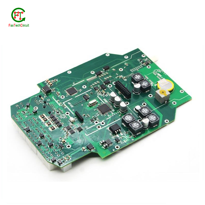
Yes, a PCB (printed circuit board) can be used for both power and signal transmission. This is commonly seen in electronic devices such as computers, smartphones, and other electronic devices. The PCB acts as a platform for connecting various components and circuits, including power sources and signal pathways. The power and signal traces on the PCB are designed to handle different levels of current and voltage to ensure efficient transmission and prevent interference between the two. However, it is important to properly design and layout the PCB to ensure proper separation and isolation of power and signal traces to avoid any potential issues.
10.What is noise coupling and how can it be prevented on a 2-layer pcb design rules?
We are a professional 2-layer pcb design rules company dedicated to providing high quality products and services.
Signal traces on a PCB (printed circuit board) are routes created to connect electronic components and allow for the transfer of electrical signals. These traces are typically made from copper and are carefully routed and designed to ensure efficient and reliable signal flow. The routing of signal traces is a critical aspect of PCB design and involves determining the best paths for the traces to minimize interference and optimize signal integrity. This is achieved through techniques such as controlled impedance routing, differential pair routing, and length-matching. Properly routing signal traces on a PCB is crucial for ensuring a functional and high-performance electronic circuit.
11.What does 2-layer pcb design rules stand for?
We attach importance to the innovation ability and team spirit of employees, have advanced R & D facilities and laboratories, and have a good quality management system.
PCB stands for Printed Circuit Board.
12.How are through-hole components soldered onto a 2-layer pcb design rules?
Through-hole components are soldered onto a printed circuit board (PCB) using a process called wave soldering. First, the PCB is fitted with all the necessary through-hole components, such as resistors, capacitors, and diodes. Then, the board is passed over a wave of molten solder, which flows through the holes in the PCB and creates a secure connection between the component and the board. The excess solder is removed and the board is inspected to ensure all components are properly soldered. This method of soldering provides a strong and reliable connection for through-hole components, making it a popular choice for electronic assembly.
13.What is the minimum thickness of a 2-layer pcb design rules?
We are committed to providing personalized solutions and established long -term strategic cooperative relationships with customers.
The minimum thickness of a PCB (printed circuit board) can vary depending on the materials and manufacturing processes used. However, the standard minimum thickness for a single-sided PCB is 0.6mm (0.024 inches) and for a double-sided PCB it is 0.8mm (0.032 inches). Thinner PCBs can be made, but they may be more fragile and have limitations on the components and circuitry that can be used.
14.What types of 2-layer pcb design ruless are there?
As one of the 2-layer pcb design rules market leaders, we are known for innovation and reliability.
There are several types of PCBs, including single-sided, double-sided, multi-layer, and flexible PCBs. Single-sided PCBs have components mounted on one side and conductive traces on the other. Double-sided PCBs have components mounted on both sides with conductive traces connecting them. Multi-layer PCBs have several layers of conductive traces and insulating material sandwiched together. Flexible PCBs are made from a flexible plastic material, allowing them to bend and twist for use in applications where traditional rigid PCBs are not suitable. Each type of PCB serves a different purpose and can be used in a variety of electronic devices and applications.
15.Can 2-layer pcb design ruless be used in automotive applications?
Yes, PCBs (printed circuit boards) can be used in automotive applications. They are commonly used in various electronic systems in vehicles, such as engine control units, infotainment systems, and safety systems. PCBs offer a compact and reliable way to connect and control electronic components in vehicles. They are also designed to withstand harsh environmental conditions, such as temperature fluctuations, vibrations, and moisture, making them suitable for use in automotive applications.
RELATED PRODUCTS & SERVICE
pcb board manufacturing How To Contact US
PCB from 1 to 30 layers, HDI, Heavy Copper, Rigid-flex board with "pcb board manufacturing One-Stop" service.

