5 button pcb board
| Base Material | FR-4/CEM-1/CEM-3/Polyimild/PTFE/Rogers |
| Board Thickness | 0.1-7mm |
| Model Number | Custom PCB & PCB Assembly |
| Type | Aluminum PCB |
| Brand Name | FC |
| Copper Thickness | 0.4-2mil(15-48um) |
| Min. Hole Size | 0.1mm(4mil)for HDI / 0.15mm(6mil) |
| Min. Line Width | 0.075mm/0.075mm(3mil/3mil) |
| Min. Line Spacing | 0.003'' |
| Surface Finishing | HASL/OSP/Ag/ENIG/ENEPIG/Immersion silver/Tin |
| Board Size | Custom |
| Model Number | Customized |
| Base Material | FR4 Aluminum CEM-1 94V0 |
| Surface Finishing | HASLENIG OSP |
| Number of layer | 1-18layer |
| Other service | Components purchasing and assem |
| ly Solder mask | White Black Green Blue,Red,etc. |
| Dsign service | Available |
| Testing | Function testing |
| Certificate | RoHS, ISO/TS16949, ISO9001 |
| Name | High Quality led light aluminum pcb printed circuit board |
| Packaging Details | Vaccum package and standard carton outside High Quality led light aluminum pcb printed circuit board |
| Supply Ability | 42344 Square Meter/Square Meters per Month |
| Quantity (pieces) | > 19068 |
| Lead time (days) | 9 |
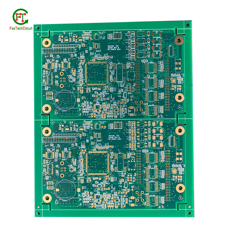
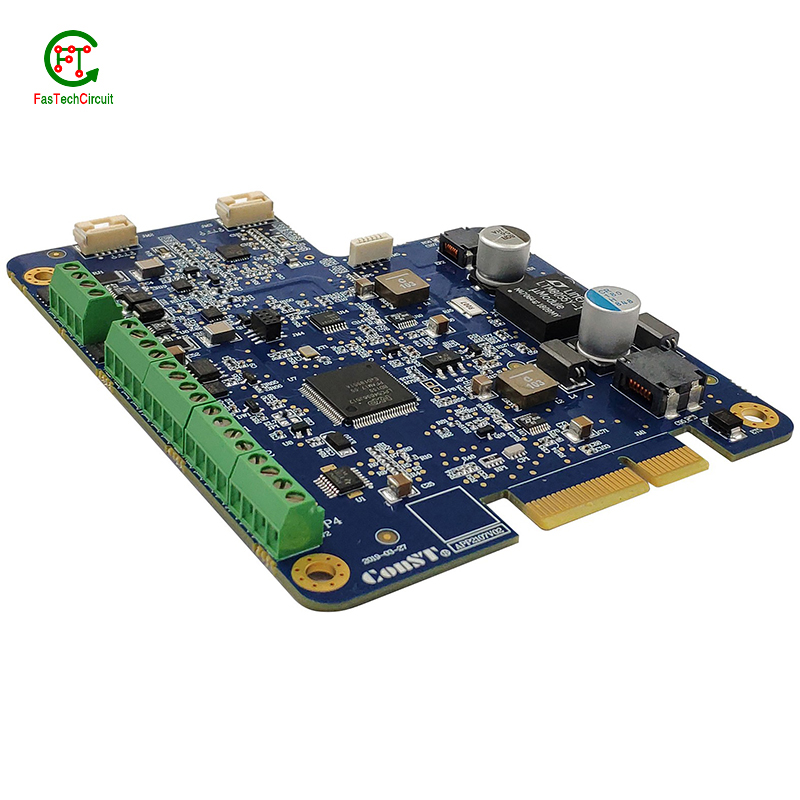
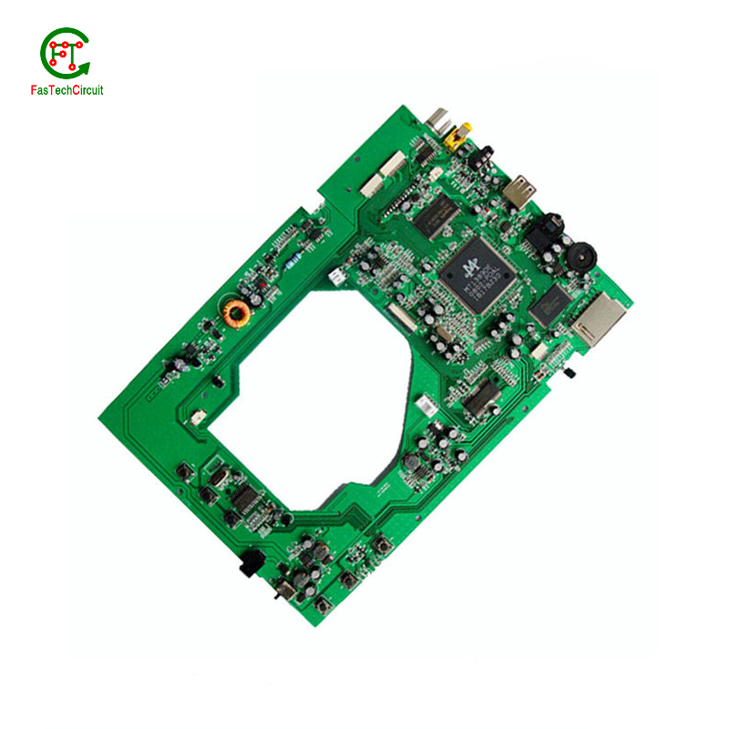
5 button pcb board bearings FAQs Guide Welcome to our state-of-the-art PCB (Printed Circuit Board) products. We are proud to offer a comprehensive range of high-quality and versatile PCB solutions to meet the constantly evolving needs of the modern electronics industry.Our PCBs are expertly designed and manufactured using the latest technology and advanced techniques, ensuring reliability, durability, and exceptional performance for a wide range of applications. We understand the importance of precision and attention to detail in the production of PCBs and we are committed to meeting stringent quality standards.
2.How are high-frequency signals handled on a 5 button pcb board?
3.Can 5 button pcb boards be used in automotive applications?
4.What is the minimum trace width and spacing on a 5 button pcb board?
5.How are components attached to a 5 button pcb board?
6.What type of solder is used for 5 button pcb board assembly?
7.What is the function of a resistor on a 5 button pcb board?
8.What are some common 5 button pcb board layout guidelines?
9.What is embedded 5 button pcb board technology?
10.What is the purpose of a 5 button pcb board?
11.How are 5 button pcb boards manufactured?
12.What is the difference between an analog and a digital signal on a 5 button pcb board?
13.How are 5 button pcb boards tested for quality control?
14.What is the role of silkscreen on a 5 button pcb board?
15.How are power and ground planes connected on a 5 button pcb board?
16.What is a through-hole component?
17.What is the difference between a gold-plated and a tin-plated 5 button pcb board?
1.What is the typical lifespan of a 5 button pcb board?
5 button pcb board is not a product only, but also can help you comes to money-making.
The typical lifespan of a PCB (printed circuit board) can vary greatly depending on various factors such as the quality of materials used, environmental conditions, and usage. In general, a well-designed and properly manufactured PCB can last for 10-20 years or more. However, some PCBs may fail prematurely due to factors such as corrosion, thermal stress, or mechanical damage. Regular maintenance and proper handling can also extend the lifespan of a PCB.
2.How are high-frequency signals handled on a 5 button pcb board?
High-frequency signals are typically handled with great care and precision on a PCB to ensure optimal performance. This involves using high-quality materials, such as high-speed laminates and low-loss dielectrics, to minimize signal loss and interference. Additionally, designers must carefully consider the trace routing and placement of components on the PCB to minimize signal reflections and keep the signal path as short and direct as possible. Specialized techniques, like controlled impedance and shielding, may also be used to further improve signal integrity.
3.Can 5 button pcb boards be used in automotive applications?
Yes, PCBs (printed circuit boards) can be used in automotive applications. They are commonly used in various electronic systems in vehicles, such as engine control units, infotainment systems, and safety systems. PCBs offer a compact and reliable way to connect and control electronic components in vehicles. They are also designed to withstand harsh environmental conditions, such as temperature fluctuations, vibrations, and moisture, making them suitable for use in automotive applications.
4.What is the minimum trace width and spacing on a 5 button pcb board?
We operate our 5 button pcb board business with integrity and honesty.
The minimum trace width and spacing on a PCB can vary depending on the manufacturing process and the specific requirements of the design. However, a common industry standard for minimum trace width and spacing is 0.006 inches (0.1524 mm). This is typically used for standard PCBs with a 1 oz copper weight. For more complex designs or higher copper weights, the minimum trace width and spacing may need to be increased to ensure proper functionality and reliability. It is important to consult with the PCB manufacturer and follow their guidelines for minimum trace width and spacing to ensure a successful design.
5.How are components attached to a 5 button pcb board?
We adhere to the principle of integrity and transparency, and establish long -term relationships with partners, and we attach great importance to this detail.
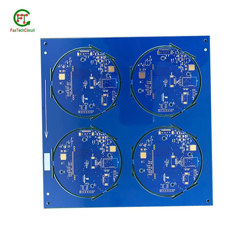
eads or pins of the component and melting solder onto them, whicComponents are attached to a PCB (printed circuit board) through a process called soldering. This involves heating the metal lh then solidifies and creates a strong electrical and mechanical connection between the component and the PCB. There are two main methods of soldering components onto a PCB:
1. Through-hole soldering: This method involves inserting the leads or pins of the component through pre-drilled holes on the PCB and soldering them on the opposite side of the board. This method is commonly used for larger components such as resistors, capacitors, and integrated circuits.
2. Surface mount soldering: This method involves soldering the component directly onto the surface of the PCB, without the need for pre-drilled holes. This is done using specialized equipment such as a soldering iron or a reflow oven. Surface mount components are smaller in size and are commonly used for more complex and compact electronic devices.
6.What type of solder is used for 5 button pcb board assembly?
The most commonly used solder for PCB assembly is a lead-free solder, specifically a tin-silver-copper (SnAgCu) alloy. This type of solder is preferred due to its high melting point, good wetting properties, and compatibility with surface mount technology (SMT) components. Other types of solder that may be used include tin-lead (SnPb) solder and lead-free alternatives such as tin-copper (SnCu) and tin-bismuth (SnBi) alloys. The specific type of solder used may vary depending on the application and industry standards.
7.What is the function of a resistor on a 5 button pcb board?
We are a new 5 button pcb board manufacturer.
The ground plane on a printed circuit board (PCB) serves as a reference point for the electrical signals that flow throughout the circuit. It is typically a large area of copper that is connected to the negative terminal of the power supply and serves as a low-impedance return path for current. Its main purpose is to provide a stable and uniform ground connection for the components on the PCB, helping to reduce electromagnetic interference and ensuring proper signal grounding. Without a ground plane, the circuit may experience noise and other unwanted effects, potentially causing malfunctions or disruptions in its functionality. Therefore, the ground plane plays a crucial role in ensuring the overall performance and reliability of a PCB.
8.What are some common 5 button pcb board layout guidelines?
We should have a stable supply chain and logistics capabilities, and provide customers with high -quality, low -priced 5 button pcb board products.
Thermal considerations play a crucial role in the design of printed circuit boards (PCBs). The concept of heat management is critical as excessive heat can lead to reduced performance and potential damage to the electronic components on the board. This is why thermal considerations are carefully taken into account during PCB design. Designers must carefully consider factors such as the size, placement, and orientation of components on the board to ensure efficient heat dissipation. They also need to factor in the type and thickness of the board material, as well as incorporate proper ventilation and heat sinks to prevent overheating. By carefully considering these thermal aspects during the design process, the resulting PCBs can perform optimally and have a longer lifespan.
9.What is embedded 5 button pcb board technology?
Our products & services cover a wide range of areas and meet the needs of different fields.
Embedded PCB technology refers to the integration of electronic components directly onto a printed circuit board (PCB) during the manufacturing process. This allows for a more compact and efficient design, as well as improved reliability and performance. The components are embedded within the layers of the PCB, rather than being mounted on the surface, resulting in a more streamlined and durable product. This technology is commonly used in applications such as smartphones, tablets, and other portable electronic devices.
10.What is the purpose of a 5 button pcb board?
We pay attention to the transformation of intellectual property protection and innovation achievements. Your OEM or ODM order design we have a complete confidentiality system.
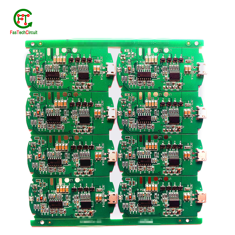
A PCB (Printed Circuit Board) is a flat board made of non-conductive material, such as fiberglass, with conductive pathways etched or printed onto it. The main purpose of a PCB is to provide a platform for electronic components to be mounted and connected together to form a functioning electronic circuit. It serves as a physical support for the components and provides a means for them to communicate with each other through the conductive pathways. PCBs are used in a wide range of electronic devices, from simple household appliances to complex computer systems, and are essential for the proper functioning and reliability of these devices. They also allow for easier and more efficient production of electronic devices, as the components can be mounted and connected in a standardized and automated manner.
11.How are 5 button pcb boards manufactured?
We have the leading technology and innovation capabilities, and attach importance to employee training and development, and provide promotion opportunities.
PCB are manufactured through a series of steps starting with designing the circuit layout. Once the design is finalized, the layout is printed on a special type of paper known as the “artwork”. This artwork is then transferred onto a copper-coated laminate board through a process called etching. The excess copper is removed, leaving behind the desired circuit pattern. The board is then drilled to create holes for components to be inserted. The next step involves adding a thin layer of solder mask to protect the circuit and adding a thin layer of copper to create traces. Finally, the components are added using a specialized machine, and the board goes through a series of tests to ensure proper functionality. Once the tests are passed, the board is cut and separated into individual PCBs for use in various electronic devices.
12.What is the difference between an analog and a digital signal on a 5 button pcb board?
An analog signal is a continuous signal that varies in amplitude and frequency over time. It can take on any value within a given range and is typically represented by a smooth, continuous waveform. Analog signals are used to transmit information such as audio, video, and sensor data.
A digital signal, on the other hand, is a discrete signal that can only take on a limited number of values. It is represented by a series of binary digits (0s and 1s) and can only have two states: on or off. Digital signals are used to transmit information in the form of data and are commonly used in digital electronics such as computers and smartphones.
On a PCB, the main difference between analog and digital signals lies in the way they are processed and transmitted. Analog signals require specialized components such as amplifiers and filters to maintain their integrity, while digital signals can be processed and transmitted using digital logic circuits. Additionally, analog signals are more susceptible to noise and interference, while digital signals are more immune to these factors.
13.How are 5 button pcb boards tested for quality control?
We have broad development space in domestic and foreign markets. 5 button pcb board have great advantages in terms of price, quality, and delivery date.
PCB (Printed Circuit Board) testing is a critical step in the quality control process of electronic products. It ensures that all components and connections on the board are functioning correctly and that the PCB meets the required standards and specifications.
The testing process typically starts with a visual inspection to identify any visible defects, such as incorrect soldering or damaged components. Next, electrical testing is conducted to check the functionality of each individual component and the overall circuit.
One common method of testing is the use of a test fixture, which applies signals to the PCB and checks for correct responses. Other methods include automated optical inspection (AOI) and in-circuit testing (ICT).
Once the initial testing is completed, the PCB may undergo environmental testing to simulate real-life conditions and ensure its reliability and durability. This includes temperature and humidity cycling, vibration and shock testing, and more.
14.What is the role of silkscreen on a 5 button pcb board?
Being one of the top 5 button pcb board manufacturers in China, We attach great importance to this detail.
Silkscreen, also known as legend or nomenclature, is a vital component of a printed circuit board (PCB). It is the layer of text and symbols that are printed on the surface of the PCB to provide essential information for component placement and identification. The silkscreen plays a crucial role in the manufacturing process of PCBs, as it helps to ensure the accuracy and functionality of the final product. By indicating component locations, values, and reference designators, the silkscreen serves as a guide for the assembly and soldering of electronic components. Additionally, it also provides important information for maintenance and troubleshooting purposes.
15.How are power and ground planes connected on a 5 button pcb board?
Power and ground planes are typically connected on a PCB through vias, which are small holes drilled through the layers of the PCB. These vias are filled with conductive material, such as copper, and allow for the flow of current between the power and ground planes. The vias are strategically placed throughout the PCB to ensure a low impedance connection between the power and ground planes. Additionally, traces or copper pours can also be used to connect the power and ground planes on different layers of the PCB.
16.What is a through-hole component?
We focus on providing high 5 button pcb board quality products and services.
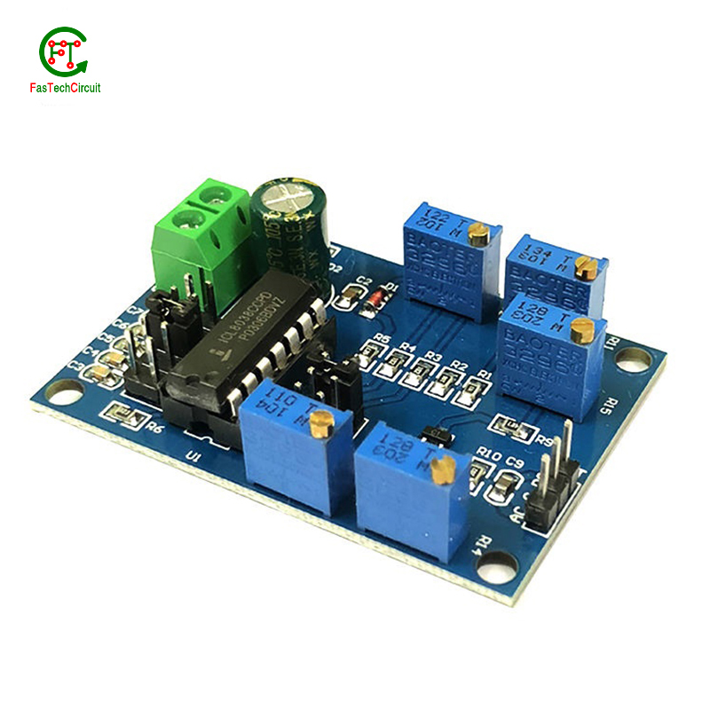
A through-hole component is an electronic component that has leads or pins that are inserted into holes on a printed circuit board (PCB) and then soldered to the opposite side of the board. This type of component is typically larger and more robust than surface mount components, and is often used for high-power or high-voltage applications. Through-hole components are also easier to replace or repair compared to surface mount components.
17.What is the difference between a gold-plated and a tin-plated 5 button pcb board?
A gold-plated PCB (Printed Circuit Board) is a type of PCB that has a thin layer of gold coating on its surface. This layer is added through a process called electroplating and is commonly used to protect the PCB components from corrosion and increase the conductivity. On the other hand, a tin-plated PCB has a layer of tin coating on its surface, which is also applied through electroplating. Unlike gold plating, tin plating is mainly used to prevent oxidization and improve solderability.
RELATED PRODUCTS & SERVICE
pcb board manufacturing How To Contact US
PCB from 1 to 30 layers, HDI, Heavy Copper, Rigid-flex board with "pcb board manufacturing One-Stop" service.
