ac30 pcb board
We can provide one-stop OEM service, and we constantly improve ourselves to keep up with international development levels. Since its establishment, we have passed ISO9001:2000, UL, TS16949:2002, ISO14001:2004 and other certifications. The purpose of our company is that quality and integrity are the lifeline! We strictly control quality to meet customers' needs, and our products are exported to more than 40 countries including North America, Europe, and Lithuania,Belize,Malta,Maldives,Egypt.
| Model Number | customized PCBA |
| Type | pcba |
| Place of Origin | Guangdong, China |
| Brand Name | none |
| Copper Thickness | 1 oz |
| Supplier Type | OEM |
| Application | Electronics Device |
| Service | One-step Service |
| Layer | 1-43layers |
| Solder mask color | Blue.green.red.black.white.etc |
| Testing Service | 100% |
| Component size | 0201-1176mm |
| Component max height | 32mm |
| Min lead pitch | 0.2mm |
| Min BGA ball pitch | 0.4mm |
| Max PCB size | 473x395mm |
| Packaging Details | Vacuum package for bare PCB and ESD package for PCBA Printed Circuit Board Factory FPC Board PCBA Companies PCBA Assembly |
| Supply Ability | 46250 Piece/Pieces per Week |
| Quantity (pieces) | > 710 |
| Lead time (days) | 12 |
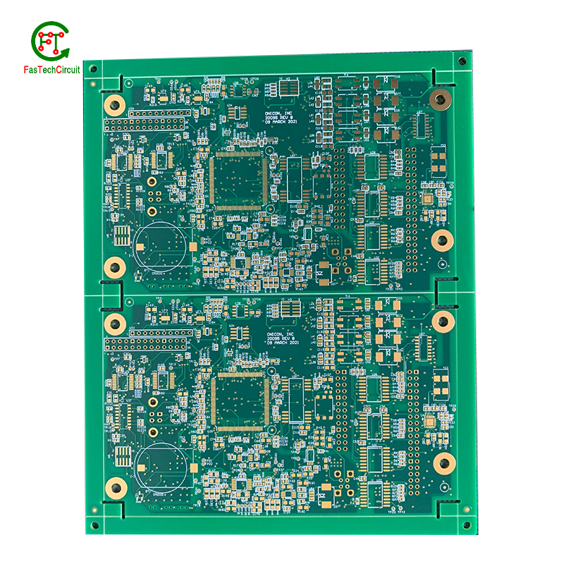
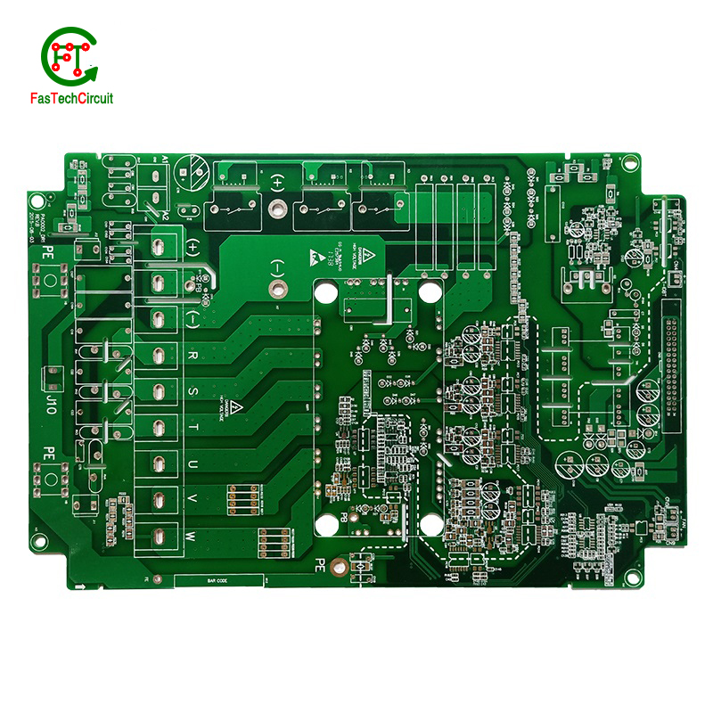
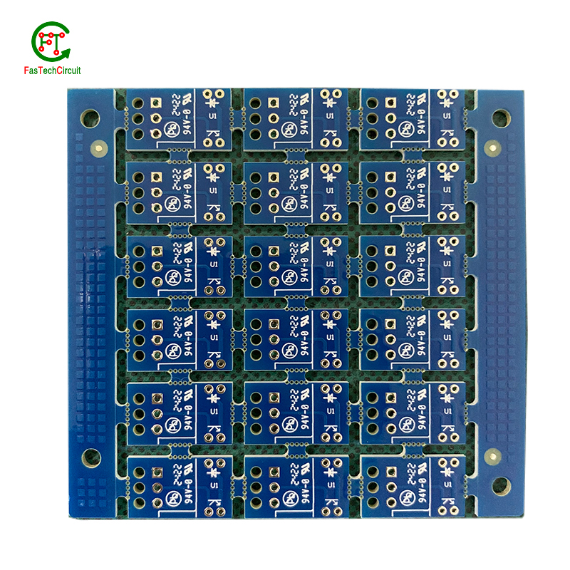
ac30 pcb board bearings FAQs Guide Welcome to our state-of-the-art PCB (Printed Circuit Board) products. We are proud to offer a comprehensive range of high-quality and versatile PCB solutions to meet the constantly evolving needs of the modern electronics industry.Our PCBs are expertly designed and manufactured using the latest technology and advanced techniques, ensuring reliability, durability, and exceptional performance for a wide range of applications. We understand the importance of precision and attention to detail in the production of PCBs and we are committed to meeting stringent quality standards.
2.What are some common problems that can occur with ac30 pcb board?
3.What are the benefits of using surface mount technology (SMT) for ac30 pcb board?
4.What is the maximum size of a ac30 pcb board?
5.What techniques are used for reducing electromagnetic interference (EMI) on a ac30 pcb board?
6.What are some common ac30 pcb board layout guidelines?
7.Can ac30 pcb boards be used for high-temperature applications?
8.What is the role of automated optical inspection (AOI) in ac30 pcb board production?
9.What type of material is used for the silkscreen on a ac30 pcb board?
10.What is the power rating for a ac30 pcb board?
11.Can ac30 pcb boards be customized?
12.What is the difference between an analog and a digital signal on a ac30 pcb board?
13.Can ac30 pcb boards be used in high-frequency applications?
14.How are high-speed/high-frequency ac30 pcb board tested and validated?
1.What materials are used to make a ac30 pcb board?
We have advanced production equipment and technology to meet the needs of customers, and can provide customers with high quality, low priced ac30 pcb board products.
A PCB, or printed circuit board, is typically made of a non-conductive material such as fiberglass or composite epoxy resin. This material acts as a base for a thin layer of copper foil, which is then etched to create the desired circuit pattern. Other common materials used in the production of PCBs include solder mask, a polymer layer used to insulate and protect the copper traces, and silkscreen, which is used to label and identify the different components on the PCB. In addition, various electronic components such as resistors, capacitors, and diodes are also mounted onto the PCB to form a functional electronic circuit. Other potential materials used in the production of PCBs include metal core, ceramics, and conductive ink, depending on the specific design and requirements of the circuit.
2.What are some common problems that can occur with ac30 pcb board?
Our ac30 pcb board products undergo strict quality control to ensure customer satisfaction.
PCB (printed circuit boards) are an integral part of electronic devices, serving as the foundation for electrical connections and components. However, like any other technology, there are certain issues that may arise with PCB. One common problem is damage to the board due to excessive heat, as electronic components generate heat and if the PCB is not properly designed or ventilated, it can lead to malfunctions or even permanent damage. Another issue is poor soldering, which can result in weak connections or no connection at all. This can be caused by inadequate equipment or inexperience in the assembly process. Additionally, PCB can also suffer from corrosion over time, especially in high humidity environments, affecting its performance and reliability. It is important to address these problems early on to prevent further damage and ensure the functionality of electronic devices. Regular maintenance, proper design and assembly techniques, and use of quality materials can help prevent these common issues with PCB.
3.What are the benefits of using surface mount technology (SMT) for ac30 pcb board?
We focus on innovation and continuous improvement to maintain a competitive advantage.
Surface mount technology (SMT) is a popular method for assembling printed circuit boards (PCBs) that offers numerous benefits over traditional through-hole components. Firstly, SMT components are smaller and more compact, allowing for greater PCB density and reducing the overall size of the board. This makes SMT ideal for increasingly miniaturized electronics, such as smartphones and wearables. Additionally, SMT components are typically cheaper and easier to manufacture, leading to cost savings in both materials and labor. SMT also allows for automated assembly, resulting in faster and more efficient production processes. Furthermore, the smaller size of SMT components leads to improved electrical performance due to decreased parasitic effects and shorter signal paths. This makes SMT ideal for high-frequency applications.
4.What is the maximum size of a ac30 pcb board?
We pay attention to the introduction and training of talents, scientifically regulate the management system, and focus on cultural construction and team cohesion.
The maximum size of a PCB (printed circuit board) can vary depending on the manufacturer and theircapabilities. However, the industry standard maximum size for a single PCB panel is typically around 18 inches by 24 inches (457 mm by 610 mm). Larger PCBs can be created by combining multiple panels together. Some manufacturers may also have the capability to create custom-sized PCBs that exceed the industry standard maximum size.
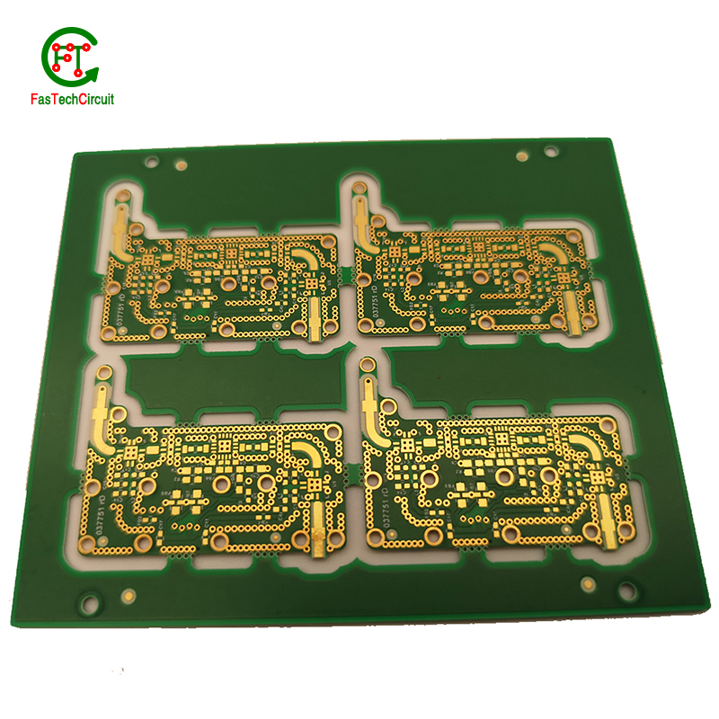
5.What techniques are used for reducing electromagnetic interference (EMI) on a ac30 pcb board?
Electromagnetic interference (EMI) is a disturbance caused by electromagnetic radiation that can disrupt the proper functioning of electronic devices. To reduce EMI on a PCB, a number of techniques can be employed. One common technique is to use a ground plane, which acts as a shield to block electromagnetic waves from interfering with the circuit. Another approach is to use proper placement and routing of components and traces to minimize the length of signal paths and reduce the chances of signal crossover. Additionally, using components like capacitors and ferrite beads can help to filter out high-frequency noise. Careful consideration and design of the PCB layout is also crucial in reducing EMI, as the placement, size, and orientation of components can impact electromagnetic emissions. By employing these techniques, EMI on a PCB can be effectively reduced, leading to improved performance and reliability of electronic devices.
6.What are some common ac30 pcb board layout guidelines?
We should have a stable supply chain and logistics capabilities, and provide customers with high -quality, low -priced ac30 pcb board products.
Thermal considerations play a crucial role in the design of printed circuit boards (PCBs). The concept of heat management is critical as excessive heat can lead to reduced performance and potential damage to the electronic components on the board. This is why thermal considerations are carefully taken into account during PCB design. Designers must carefully consider factors such as the size, placement, and orientation of components on the board to ensure efficient heat dissipation. They also need to factor in the type and thickness of the board material, as well as incorporate proper ventilation and heat sinks to prevent overheating. By carefully considering these thermal aspects during the design process, the resulting PCBs can perform optimally and have a longer lifespan.
7.Can ac30 pcb boards be used for high-temperature applications?
Yes, PCBs (printed circuit boards) can be used for high-temperature applications. However, the materials and design of the PCB must be carefully chosen to ensure that it can withstand the high temperatures without degrading or malfunctioning.
Some factors to consider when using PCBs for high-temperature applications include the type of substrate material, the type of solder used, and the thickness of the copper traces. High-temperature substrates such as ceramic or polyimide can withstand temperatures up to 300°C, while standard FR4 substrates are only suitable for temperatures up to 130°C.
Specialized solder materials, such as high-temperature lead-free solders, may also be necessary to ensure the reliability of the PCB at high temperatures. Additionally, thicker copper traces can help dissipate heat more effectively and prevent damage to the PCB.
8.What is the role of automated optical inspection (AOI) in ac30 pcb board production?
Automated optical inspection (AOI) plays a crucial role in the production of printed circuit boards (PCBs). It is a technology that uses advanced imaging techniques to detect and identify defects or errors on a PCB, such as missing components, incorrect placement, and faulty soldering. AOI has become an essential step in the production process as it helps manufacturers ensure the quality and reliability of their PCBs. By detecting and identifying defects at an early stage, AOI can significantly reduce the number of defects and increase the efficiency of the production process. Furthermore, AOI is able to perform inspections at a much faster rate and with higher accuracy compared to manual inspection, making it an indispensable tool for PCB production.
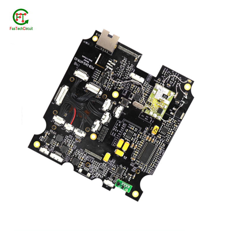
9.What type of material is used for the silkscreen on a ac30 pcb board?
We have a wide range of ac30 pcb board customer groups and establishes long -term cooperative relationships with partners. The countries we provide services include .
The material used for the silkscreen on a PCB is typically a white or black ink made of epoxy or acrylic. It is applied using a screen printing process and is cured at high temperatures to ensure durability and resistance to chemicals and solvents.
10.What is the power rating for a ac30 pcb board?
We maintain a certain amount of R&D investment every year and continuously improve operational efficiency to provide better services to our cooperative customers.
The power rating for a PCB (printed circuit board) can vary greatly depending on its size, design, and intended use. Generally, the power rating for a PCB is determined by the maximum amount of current it can safely handle without overheating or causing damage. This can range from a few milliamps for small, low-power circuits to several amps for larger, high-power circuits. It is important to consult the manufacturer's specifications or consult with an engineer to determine the specific power rating for a particular PCB.
11.Can ac30 pcb boards be customized?
We should enjoy a good reputation in the industry, and we can increase the added value of the products of cooperative customers through technological innovation.
Yes, PCBs (printed circuit boards) can be customized to meet specific design requirements. This can include changes to the size, shape, number of layers, and placement of components on the board. Customization can also involve the use of specialized materials, finishes, and manufacturing processes to meet specific performance or environmental requirements. PCB manufacturers often offer design services to help customers create custom PCBs that meet their unique needs.
12.What is the difference between an analog and a digital signal on a ac30 pcb board?
An analog signal is a continuous signal that varies in amplitude and frequency over time. It can take on any value within a given range and is typically represented by a smooth, continuous waveform. Analog signals are used to transmit information such as audio, video, and sensor data.
A digital signal, on the other hand, is a discrete signal that can only take on a limited number of values. It is represented by a series of binary digits (0s and 1s) and can only have two states: on or off. Digital signals are used to transmit information in the form of data and are commonly used in digital electronics such as computers and smartphones.
On a PCB, the main difference between analog and digital signals lies in the way they are processed and transmitted. Analog signals require specialized components such as amplifiers and filters to maintain their integrity, while digital signals can be processed and transmitted using digital logic circuits. Additionally, analog signals are more susceptible to noise and interference, while digital signals are more immune to these factors.
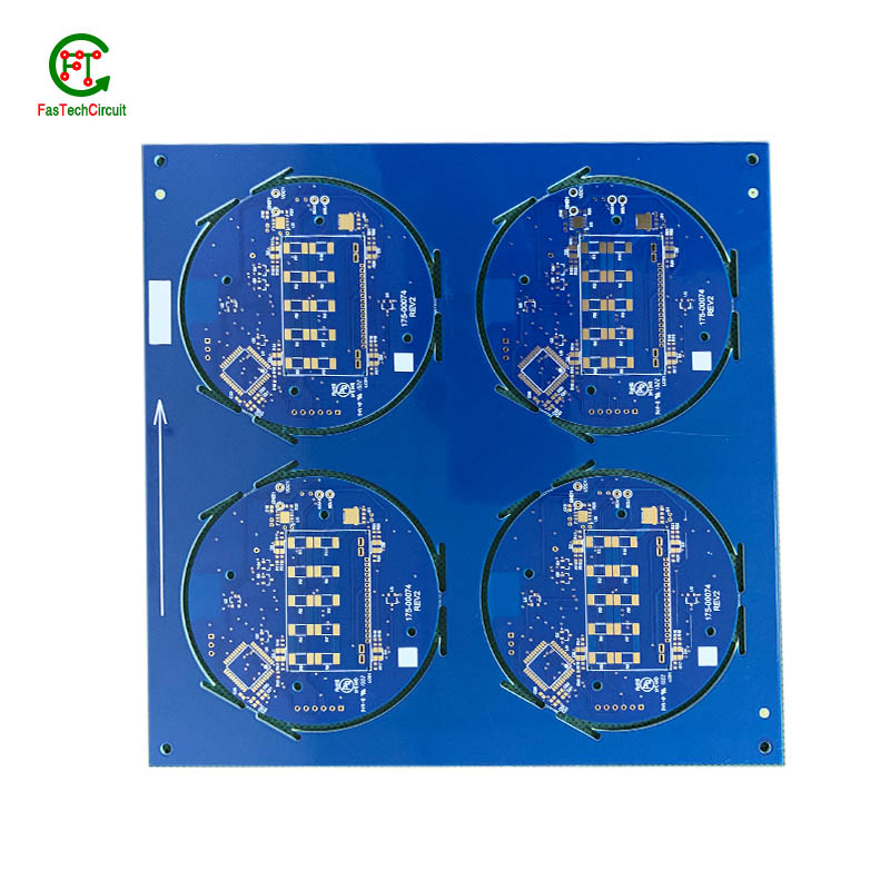
13.Can ac30 pcb boards be used in high-frequency applications?
Our mission is to provide customers with the best solutions for ac30 pcb board.
Yes, PCBs (printed circuit boards) can be used in high-frequency applications. However, the design and construction of the PCB must be carefully considered to ensure optimal performance at high frequencies. This includes using specialized materials, such as high-frequency laminates, and implementing proper grounding and shielding techniques. Additionally, the layout and routing of the PCB must be optimized to minimize signal loss and interference.
14.How are high-speed/high-frequency ac30 pcb board tested and validated?
Testing and validation are essential steps in the production process of high-speed and high-frequency printed circuit boards (PCBs). These specialized types of PCBs are used in a wide range of industries, including telecommunications, aerospace, and automotive, and require precision and reliability in their performance.
The testing and validation process for high-speed/high-frequency PCBs involves several steps to ensure that the final product meets the required specifications. This starts with design simulation and analysis using specialized software to verify the layout and electrical characteristics of the PCB.
Once the design is confirmed, prototype PCBs are manufactured and subjected to various tests, including signal integrity and power integrity tests. These tests evaluate the electrical performance of the PCB, such as its ability to transmit signals at high speeds and maintain signal integrity.
In addition to electrical tests, environmental and mechanical tests are also performed to assess the durability and reliability of the PCB under different conditions, such as temperature changes and mechanical stress.
The final step in the testing and validation process is the inspection and analysis of the tested PCBs. This involves a detailed review of the test results and any necessary modifications to meet the required specifications.
RELATED PRODUCTS & SERVICE
pcb board manufacturing How To Contact US
PCB from 1 to 30 layers, HDI, Heavy Copper, Rigid-flex board with "pcb board manufacturing One-Stop" service.

