600-001532 rev a pcb ic board
As an IS09001 quality system certified supplier, we have accumulated rich experience in PCBA assembly and product manufacturing, and we can provide one-stop OEM services! And implement strict quality management, which gives us a good reputation in the same industry. Our (EMS) processing services cover almost every industry, including: industrial control, consumer electronics, automotive electronics, medical, security, electrical appliances, agriculture and national defense, aerospace, etc. With different product introduction experience, our account managers and projects The team will work closely with clients to fully understand their needs and strive to exceed them. We have won high praise from customers from Europe, America, Asia, Andorra,Greece,Namibia,India,Bhutan... and so on.
| Base Material | FR-4/CEM-1/CEM-3/Polyimild/PTFE/Rogers |
| Board Thickness | 0.2-8mm |
| Model Number | Custom PCB & PCB Assembly |
| Type | Aluminum PCB |
| Brand Name | FC |
| Copper Thickness | 0.4-2mil(14-57um) |
| Min. Hole Size | 0.1mm(4mil)for HDI / 0.15mm(6mil) |
| Min. Line Width | 0.075mm/0.075mm(3mil/3mil) |
| Min. Line Spacing | 0.003'' |
| Surface Finishing | HASL/OSP/Ag/ENIG/ENEPIG/Immersion silver/Tin |
| Board Size | Custom |
| Model Number | Customized |
| Base Material | FR4 Aluminum CEM-1 94V0 |
| Surface Finishing | HASLENIG OSP |
| Number of layer | 1-12layer |
| Other service | Components purchasing and assem |
| ly Solder mask | White Black Green Blue,Red,etc. |
| Dsign service | Available |
| Testing | Function testing |
| Certificate | RoHS, ISO/TS16949, ISO9001 |
| Name | High Quality led light aluminum pcb printed circuit board |
| Packaging Details | Vaccum package and standard carton outside High Quality led light aluminum pcb printed circuit board |
| Supply Ability | 43117 Square Meter/Square Meters per Month |
| Quantity (pieces) | > 17533 |
| Lead time (days) | 11 |
600-001532 rev a pcb ic board bearings FAQs Guide Welcome to our state-of-the-art PCB (Printed Circuit Board) products. We are proud to offer a comprehensive range of high-quality and versatile PCB solutions to meet the constantly evolving needs of the modern electronics industry.Our PCBs are expertly designed and manufactured using the latest technology and advanced techniques, ensuring reliability, durability, and exceptional performance for a wide range of applications. We understand the importance of precision and attention to detail in the production of PCBs and we are committed to meeting stringent quality standards.
2.How are 600-001532 rev a pcb ic boards tested for quality control?
3.What is the minimum trace width and spacing on a 600-001532 rev a pcb ic board?
4.How are thermal considerations taken into account during 600-001532 rev a pcb ic board design?
5.What does 600-001532 rev a pcb ic board stand for?
6.What is the function of a decoupling capacitor on a 600-001532 rev a pcb ic board?
7.How are holes drilled into a 600-001532 rev a pcb ic board?
8.What is the lifespan of a 600-001532 rev a pcb ic board under harsh environmental conditions?
9.Can 600-001532 rev a pcb ic boards be used for high-temperature applications?
10.What is the maximum operating temperature of a 600-001532 rev a pcb ic board?
11.What are the main components of a 600-001532 rev a pcb ic board?
12.What types of 600-001532 rev a pcb ic boards are there?
13.How are high-speed/high-frequency 600-001532 rev a pcb ic board tested and validated?
14.What is the process of etching a 600-001532 rev a pcb ic board?
15.What are some common problems that can occur with 600-001532 rev a pcb ic board?
16.Can 600-001532 rev a pcb ic boards be customized?
1.What is the difference between an analog and a digital signal on a 600-001532 rev a pcb ic board?
An analog signal is a continuous signal that varies in amplitude and frequency over time. It can take on any value within a given range and is typically represented by a smooth, continuous waveform. Analog signals are used to transmit information such as audio, video, and sensor data.
A digital signal, on the other hand, is a discrete signal that can only take on a limited number of values. It is represented by a series of binary digits (0s and 1s) and can only have two states: on or off. Digital signals are used to transmit information in the form of data and are commonly used in digital electronics such as computers and smartphones.
On a PCB, the main difference between analog and digital signals lies in the way they are processed and transmitted. Analog signals require specialized components such as amplifiers and filters to maintain their integrity, while digital signals can be processed and transmitted using digital logic circuits. Additionally, analog signals are more susceptible to noise and interference, while digital signals are more immune to these factors.
2.How are 600-001532 rev a pcb ic boards tested for quality control?
We have broad development space in domestic and foreign markets. 600-001532 rev a pcb ic board have great advantages in terms of price, quality, and delivery date.
PCB (Printed Circuit Board) testing is a critical step in the quality control process of electronic products. It ensures that all components and connections on the board are functioning correctly and that the PCB meets the required standards and specifications.
The testing process typically starts with a visual inspection to identify any visible defects, such as incorrect soldering or damaged components. Next, electrical testing is conducted to check the functionality of each individual component and the overall circuit.
One common method of testing is the use of a test fixture, which applies signals to the PCB and checks for correct responses. Other methods include automated optical inspection (AOI) and in-circuit testing (ICT).
Once the initial testing is completed, the PCB may undergo environmental testing to simulate real-life conditions and ensure its reliability and durability. This includes temperature and humidity cycling, vibration and shock testing, and more.
3.What is the minimum trace width and spacing on a 600-001532 rev a pcb ic board?
We operate our 600-001532 rev a pcb ic board business with integrity and honesty.
The minimum trace width and spacing on a PCB can vary depending on the manufacturing process and the specific requirements of the design. However, a common industry standard for minimum trace width and spacing is 0.006 inches (0.1524 mm). This is typically used for standard PCBs with a 1 oz copper weight. For more complex designs or higher copper weights, the minimum trace width and spacing may need to be increased to ensure proper functionality and reliability. It is important to consult with the PCB manufacturer and follow their guidelines for minimum trace width and spacing to ensure a successful design.
4.How are thermal considerations taken into account during 600-001532 rev a pcb ic board design?
As one of the top 600-001532 rev a pcb ic board manufacturers in China, we take this very seriously.
Thermal considerations are crucial in the design of printed circuit boards (PCB), as excessive heat can greatly affect the performance and lifespan of electronic components. PCB design engineers must carefully consider thermal management strategies, such as proper placement of heat-generating components, effective heat dissipation techniques, and optimal selection of materials. Thermal simulations and analysis are also commonly used to evaluate and optimize the PCB design to ensure that the temperature of the PCB and its components are within safe limits. By taking into account these thermal considerations, the finished PCB can perform reliably and efficiently, ensuring the overall quality and function of electronic devices.
5.What does 600-001532 rev a pcb ic board stand for?
We attach importance to the innovation ability and team spirit of employees, have advanced R & D facilities and laboratories, and have a good quality management system.
PCB stands for Printed Circuit Board.
6.What is the function of a decoupling capacitor on a 600-001532 rev a pcb ic board?
We have rich industry experience and professional knowledge, and have strong competitiveness in the market.
A decoupling capacitor is a type of capacitor that is used to reduce or eliminate noise and interference in electronic circuits. It is typically placed on a PCB (printed circuit board) near the power supply pins of an integrated circuit (IC) or other active component.
The main function of a decoupling capacitor is to provide a stable and clean power supply to the IC or other active component. This is achieved by filtering out high-frequency noise and voltage fluctuations that can be caused by other components on the PCB or external sources.
In addition, a decoupling capacitor also helps to prevent voltage drops and spikes that can occur when the IC or other component suddenly draws a large amount of current. This is especially important for sensitive components that require a stable power supply to function properly.
7.How are holes drilled into a 600-001532 rev a pcb ic board?
We actively participate in the 600-001532 rev a pcb ic board industry associations and organization activities. The corporate social responsibility performed well, and the focus of brand building and promotion.
Drilling holes into printed circuit boards (PCBs) is a critical part of the PCB manufacturing process. These holes are used for mounting electronic components and for creating electrical connections between different layers of the board. There are two main methods for drilling holes into a PCB – mechanical drilling and laser drilling. Mechanical drilling involves using a high speed drill bit to physically drill through the board, while laser drilling uses a high-powered laser to vaporize the material and create the holes. Both methods have their own advantages and are often used in combination to achieve the desired hole sizes and precision. Regardless of the method, the holes are carefully planned and executed to ensure the successful production of a high-quality PCB.
8.What is the lifespan of a 600-001532 rev a pcb ic board under harsh environmental conditions?
The lifespan of a PCB (printed circuit board) under harsh environmental conditions can vary greatly depending on the specific conditions and the quality of the PCB. In general, a well-designed and high-quality PCB can last for 10-20 years under harsh conditions such as extreme temperatures, humidity, and exposure to chemicals or vibrations. However, if the PCB is not properly designed or manufactured, its lifespan can be significantly shorter, potentially lasting only a few years or even months. Factors such as the type of materials used, the thickness of the copper traces, and the quality of the solder joints can also affect the lifespan of a PCB under harsh environmental conditions. Regular maintenance and proper handling can also help extend the lifespan of a PCB.
9.Can 600-001532 rev a pcb ic boards be used for high-temperature applications?
Yes, PCBs (printed circuit boards) can be used for high-temperature applications. However, the materials and design of the PCB must be carefully chosen to ensure that it can withstand the high temperatures without degrading or malfunctioning.
Some factors to consider when using PCBs for high-temperature applications include the type of substrate material, the type of solder used, and the thickness of the copper traces. High-temperature substrates such as ceramic or polyimide can withstand temperatures up to 300°C, while standard FR4 substrates are only suitable for temperatures up to 130°C.
Specialized solder materials, such as high-temperature lead-free solders, may also be necessary to ensure the reliability of the PCB at high temperatures. Additionally, thicker copper traces can help dissipate heat more effectively and prevent damage to the PCB.
10.What is the maximum operating temperature of a 600-001532 rev a pcb ic board?
We have a professional team that is committed to the innovation and development of 600-001532 rev a pcb ic board.
The maximum operating temperature of a PCB (printed circuit board) can vary depending on the materials and components used in its construction. Generally, the maximum operating temperature for a standard FR4 PCB is around 130-140 degrees Celsius. However, specialized materials such as high-temperature laminates or ceramic substrates can withstand higher temperatures up to 200-250 degrees Celsius. The maximum operating temperature of a PCB should always be determined by the manufacturer's specifications and guidelines.
11.What are the main components of a 600-001532 rev a pcb ic board?
We continuously upgrade our skills and knowledge to adapt to changing 600-001532 rev a pcb ic board market needs.
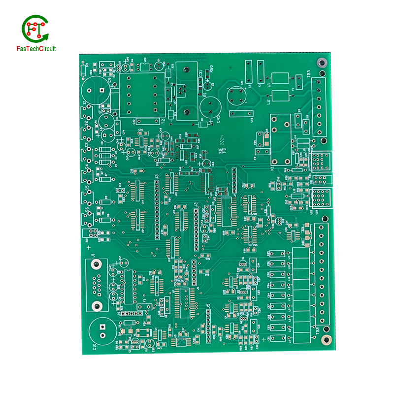
A typical PCB consists of several vital components, including a substrate material, copper traces, solder mask, silk screen, and plated through-holes. The substrate material acts as the base and provides mechanical support for the board. Copper traces, usually made of thin lines of copper foil, serve as the conductive paths for transmitting electrical signals. The solder mask, applied as a protective layer, prevents accidental short circuits and corrosion. Silk screen, a layer of ink-based labeling, aids in component identification. Lastly, plated through-holes enable electrical connection between different layers of the PCB board. These components work together to form a fully functioning PCB.
12.What types of 600-001532 rev a pcb ic boards are there?
As one of the 600-001532 rev a pcb ic board market leaders, we are known for innovation and reliability.
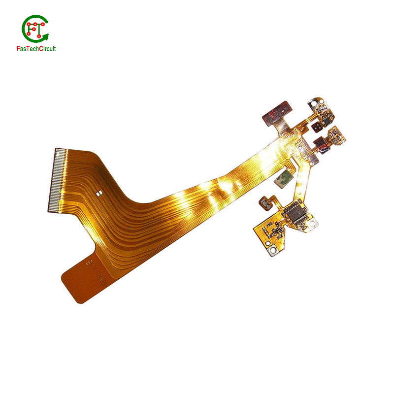
There are several types of PCBs, including single-sided, double-sided, multi-layer, and flexible PCBs. Single-sided PCBs have components mounted on one side and conductive traces on the other. Double-sided PCBs have components mounted on both sides with conductive traces connecting them. Multi-layer PCBs have several layers of conductive traces and insulating material sandwiched together. Flexible PCBs are made from a flexible plastic material, allowing them to bend and twist for use in applications where traditional rigid PCBs are not suitable. Each type of PCB serves a different purpose and can be used in a variety of electronic devices and applications.
13.How are high-speed/high-frequency 600-001532 rev a pcb ic board tested and validated?
Testing and validation are essential steps in the production process of high-speed and high-frequency printed circuit boards (PCBs). These specialized types of PCBs are used in a wide range of industries, including telecommunications, aerospace, and automotive, and require precision and reliability in their performance.
The testing and validation process for high-speed/high-frequency PCBs involves several steps to ensure that the final product meets the required specifications. This starts with design simulation and analysis using specialized software to verify the layout and electrical characteristics of the PCB.
Once the design is confirmed, prototype PCBs are manufactured and subjected to various tests, including signal integrity and power integrity tests. These tests evaluate the electrical performance of the PCB, such as its ability to transmit signals at high speeds and maintain signal integrity.
In addition to electrical tests, environmental and mechanical tests are also performed to assess the durability and reliability of the PCB under different conditions, such as temperature changes and mechanical stress.
The final step in the testing and validation process is the inspection and analysis of the tested PCBs. This involves a detailed review of the test results and any necessary modifications to meet the required specifications.
14.What is the process of etching a 600-001532 rev a pcb ic board?
We have flexible production capacity. Whether you are large orders or small orders, you can produce and release goods in a timely manner to meet customer needs.
PCB (Printed Circuit Board) etching is the process of creating a circuit pattern on a copper-clad board by using chemical etchants to selectively remove the unwanted copper. The process begins by transferring the circuit design onto a copper-clad board using various methods such as printing or photolithography. Next, the board is coated with a resist material, which protects the areas of copper that will eventually become the circuit traces. The board is then placed in an etching solution, typically a mixture of acid and water, which dissolves the unprotected copper. Once the desired circuit pattern is etched into the board, the resist material is removed, and the board is cleaned and inspected for any imperfections. PCB etching is a crucial step in the manufacturing of PCBs, as it creates the necessary conductive pathways for electronic components to be mounted and interconnected, making it an essential process in the production of electronic devices.
15.What are some common problems that can occur with 600-001532 rev a pcb ic board?
Our 600-001532 rev a pcb ic board products undergo strict quality control to ensure customer satisfaction.
PCB (printed circuit boards) are an integral part of electronic devices, serving as the foundation for electrical connections and components. However, like any other technology, there are certain issues that may arise with PCB. One common problem is damage to the board due to excessive heat, as electronic components generate heat and if the PCB is not properly designed or ventilated, it can lead to malfunctions or even permanent damage. Another issue is poor soldering, which can result in weak connections or no connection at all. This can be caused by inadequate equipment or inexperience in the assembly process. Additionally, PCB can also suffer from corrosion over time, especially in high humidity environments, affecting its performance and reliability. It is important to address these problems early on to prevent further damage and ensure the functionality of electronic devices. Regular maintenance, proper design and assembly techniques, and use of quality materials can help prevent these common issues with PCB.
16.Can 600-001532 rev a pcb ic boards be customized?
We should enjoy a good reputation in the industry, and we can increase the added value of the products of cooperative customers through technological innovation.
Yes, PCBs (printed circuit boards) can be customized to meet specific design requirements. This can include changes to the size, shape, number of layers, and placement of components on the board. Customization can also involve the use of specialized materials, finishes, and manufacturing processes to meet specific performance or environmental requirements. PCB manufacturers often offer design services to help customers create custom PCBs that meet their unique needs.
RELATED PRODUCTS & SERVICE
pcb board manufacturing How To Contact US
PCB from 1 to 30 layers, HDI, Heavy Copper, Rigid-flex board with "pcb board manufacturing One-Stop" service.

