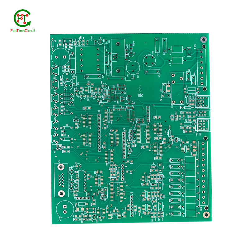
6502 pcb board
As an IS09001 quality system certified supplier, we have accumulated rich experience in PCBA assembly and product manufacturing, and we can provide one-stop OEM services! And implement strict quality management, which gives us a good reputation in the same industry. Our (EMS) processing services cover almost every industry, including: industrial control, consumer electronics, automotive electronics, medical, security, electrical appliances, agriculture and national defense, aerospace, etc. With different product introduction experience, our account managers and projects The team will work closely with clients to fully understand their needs and strive to exceed them. We have won high praise from customers from Europe, America, Asia, Haiti,British Indian Ocean Territory,Maldives... and so on.
| Number of Layers | 4 layer |
| Base Material | gold sinking |
| Board Thickness | 3.2MM |
| Board Size | 342M*556MM |
| Model Number | 4 layer pcb |
| Type | pcb |
| Place of Origin | Original |
| Brand Name | Original |
| Copper Thickness | 3OZ |
| Min. Hole Size | custom made |
| Min. Line Width | custom made |
| Min. Line Spacing | custom made |
| Surface Finishing | custom made |
| Impedance control | +/- 9% |
| Warpage | less than 1% |
| Packaging Details | New and Original, factory sealed packing, it will be pack in one of these packing type: Tube, Tray, Tape and Reel, Tape and Box, Bulk packing, Bag and etc. Please kindly contact us for more details. |
| Supply Ability | 5844 Piece/Pieces per Week |
| Quantity (pieces) | > 18793 |
| Lead time (days) | 10 |
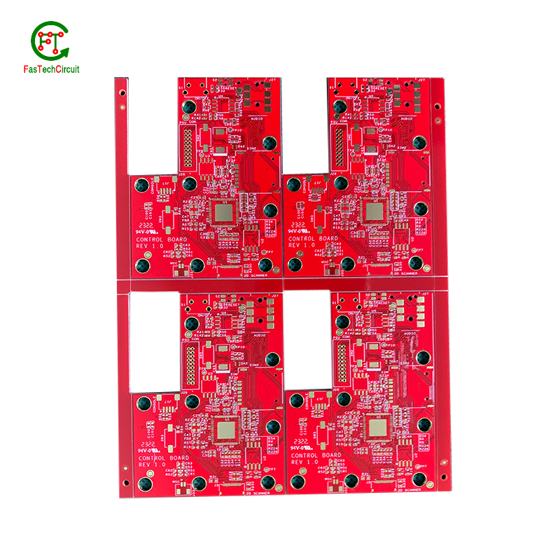
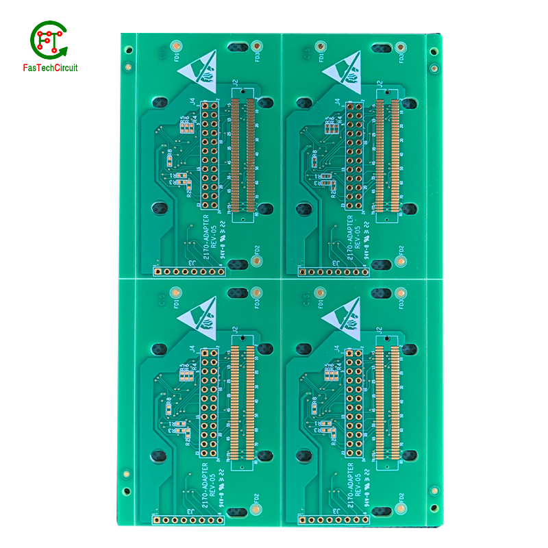
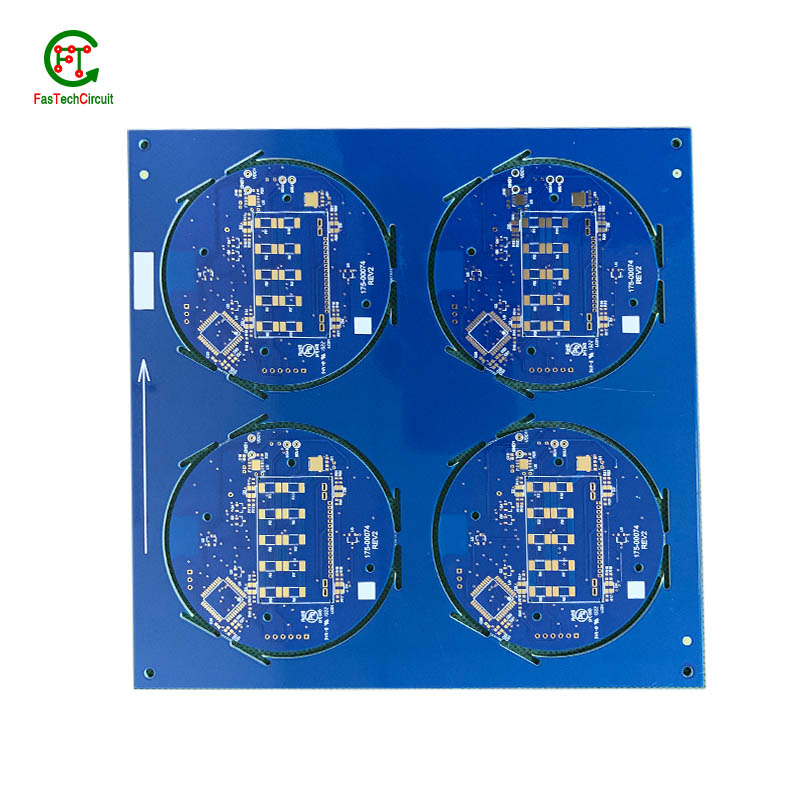
6502 pcb board bearings FAQs Guide Welcome to our state-of-the-art PCB (Printed Circuit Board) products. We are proud to offer a comprehensive range of high-quality and versatile PCB solutions to meet the constantly evolving needs of the modern electronics industry.Our PCBs are expertly designed and manufactured using the latest technology and advanced techniques, ensuring reliability, durability, and exceptional performance for a wide range of applications. We understand the importance of precision and attention to detail in the production of PCBs and we are committed to meeting stringent quality standards.
2.What are the benefits of using surface mount technology (SMT) for 6502 pcb board?
3.How are high-speed/high-frequency 6502 pcb board tested and validated?
4.What is the future outlook for 6502 pcb board technology?
5.What is the role of vias on a 6502 pcb board?
6.Can 6502 pcb boards be customized?
7.What software is used for 6502 pcb board design?
8.Can a 6502 pcb board be used for both power and signal transmission?
9.How are 6502 pcb boards manufactured?
10.Can 6502 pcb boards be used for high-temperature applications?
11.What is the minimum thickness of a 6502 pcb board?
12.What are the most common uses for 6502 pcb board?
13.How are holes drilled into a 6502 pcb board?
14.What materials are used to make a 6502 pcb board?
15.How are 6502 pcb boards protected from environmental factors?
1.What are the advantages of using a 6502 pcb board?
We are centered on customers and always pay attention to customers' needs for 6502 pcb board products.
There are several advantages of using a PCB (Printed Circuit Board). Firstly, a PCB provides a compact and organized layout for electronic components, which makes it easier for technicians to troubleshoot and repair any issues. Secondly, it reduces the chances of loose connections and short circuits, which can be a major safety concern. Thirdly, PCBs are cost-effective and can be easily mass-produced, making them a popular choice for large-scale production. Additionally, they offer durability and stability, ensuring long-lasting performance. Finally, PCBs also allow for easy integration of new components, making it easier to upgrade or modify the electronic devices.
2.What are the benefits of using surface mount technology (SMT) for 6502 pcb board?
We focus on innovation and continuous improvement to maintain a competitive advantage.
Surface mount technology (SMT) is a popular method for assembling printed circuit boards (PCBs) that offers numerous benefits over traditional through-hole components. Firstly, SMT components are smaller and more compact, allowing for greater PCB density and reducing the overall size of the board. This makes SMT ideal for increasingly miniaturized electronics, such as smartphones and wearables. Additionally, SMT components are typically cheaper and easier to manufacture, leading to cost savings in both materials and labor. SMT also allows for automated assembly, resulting in faster and more efficient production processes. Furthermore, the smaller size of SMT components leads to improved electrical performance due to decreased parasitic effects and shorter signal paths. This makes SMT ideal for high-frequency applications.
3.How are high-speed/high-frequency 6502 pcb board tested and validated?
Testing and validation are essential steps in the production process of high-speed and high-frequency printed circuit boards (PCBs). These specialized types of PCBs are used in a wide range of industries, including telecommunications, aerospace, and automotive, and require precision and reliability in their performance.
The testing and validation process for high-speed/high-frequency PCBs involves several steps to ensure that the final product meets the required specifications. This starts with design simulation and analysis using specialized software to verify the layout and electrical characteristics of the PCB.
Once the design is confirmed, prototype PCBs are manufactured and subjected to various tests, including signal integrity and power integrity tests. These tests evaluate the electrical performance of the PCB, such as its ability to transmit signals at high speeds and maintain signal integrity.
In addition to electrical tests, environmental and mechanical tests are also performed to assess the durability and reliability of the PCB under different conditions, such as temperature changes and mechanical stress.
The final step in the testing and validation process is the inspection and analysis of the tested PCBs. This involves a detailed review of the test results and any necessary modifications to meet the required specifications.
4.What is the future outlook for 6502 pcb board technology?
Printed Circuit Boards, or PCBs, have been a vital component in electronic devices for decades. They serve as the foundation for the electrical connections and components that make our devices function properly. As technology continues to advance, so does the demand for smaller, faster, and more efficient PCBs. With the rise of IoT and smart devices, the future outlook for PCB technology is promising. It is expected that PCBs will become even more compact and complex, utilizing advanced materials and techniques such as 3D printing and flexible substrates. This will not only improve the performance of electronic devices, but also make them more durable and cost-effective. Furthermore, as sustainability becomes a growing concern, eco-friendly PCB materials and manufacturing processes are being developed to reduce environmental impact. With these advancements, it is safe to say that the future of PCB technology is bright and full of endless possibilities.
5.What is the role of vias on a 6502 pcb board?
Our company has many years of 6502 pcb board experience and expertise.
Vias play a crucial role in connecting different layers of a printed circuit board (PCB). These small, plated holes act as conductive paths, allowing signals and power to pass through the board and reach various components. Vias are also essential for routing traces from one layer to another, optimizing the layout and reducing the size and complexity of the board. Additionally, vias provide structural support and improve thermal management by facilitating heat dissipation.
6.Can 6502 pcb boards be customized?
We should enjoy a good reputation in the industry, and we can increase the added value of the products of cooperative customers through technological innovation.
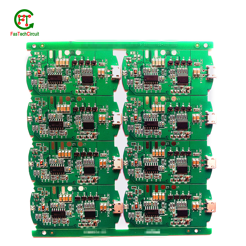
Yes, PCBs (printed circuit boards) can be customized to meet specific design requirements. This can include changes to the size, shape, number of layers, and placement of components on the board. Customization can also involve the use of specialized materials, finishes, and manufacturing processes to meet specific performance or environmental requirements. PCB manufacturers often offer design services to help customers create custom PCBs that meet their unique needs.
7.What software is used for 6502 pcb board design?
Our 6502 pcb board products have competitive and differentiated advantages, and actively promote digital transformation and innovation.
Some popular software used for PCB design include:
1. Altium Designer
2. Eagle PCB
3. KiCad
4. OrCAD
5. PADS
6. Proteus
7. DipTrace
8. EasyEDA
9. CircuitMaker
10. DesignSpark PCB
8.Can a 6502 pcb board be used for both power and signal transmission?
Yes, a PCB (printed circuit board) can be used for both power and signal transmission. This is commonly seen in electronic devices such as computers, smartphones, and other electronic devices. The PCB acts as a platform for connecting various components and circuits, including power sources and signal pathways. The power and signal traces on the PCB are designed to handle different levels of current and voltage to ensure efficient transmission and prevent interference between the two. However, it is important to properly design and layout the PCB to ensure proper separation and isolation of power and signal traces to avoid any potential issues.
9.How are 6502 pcb boards manufactured?
We have the leading technology and innovation capabilities, and attach importance to employee training and development, and provide promotion opportunities.
PCB are manufactured through a series of steps starting with designing the circuit layout. Once the design is finalized, the layout is printed on a special type of paper known as the “artwork”. This artwork is then transferred onto a copper-coated laminate board through a process called etching. The excess copper is removed, leaving behind the desired circuit pattern. The board is then drilled to create holes for components to be inserted. The next step involves adding a thin layer of solder mask to protect the circuit and adding a thin layer of copper to create traces. Finally, the components are added using a specialized machine, and the board goes through a series of tests to ensure proper functionality. Once the tests are passed, the board is cut and separated into individual PCBs for use in various electronic devices.
10.Can 6502 pcb boards be used for high-temperature applications?
Yes, PCBs (printed circuit boards) can be used for high-temperature applications. However, the materials and design of the PCB must be carefully chosen to ensure that it can withstand the high temperatures without degrading or malfunctioning.
Some factors to consider when using PCBs for high-temperature applications include the type of substrate material, the type of solder used, and the thickness of the copper traces. High-temperature substrates such as ceramic or polyimide can withstand temperatures up to 300°C, while standard FR4 substrates are only suitable for temperatures up to 130°C.
Specialized solder materials, such as high-temperature lead-free solders, may also be necessary to ensure the reliability of the PCB at high temperatures. Additionally, thicker copper traces can help dissipate heat more effectively and prevent damage to the PCB.
11.What is the minimum thickness of a 6502 pcb board?
We are committed to providing personalized solutions and established long -term strategic cooperative relationships with customers.
The minimum thickness of a PCB (printed circuit board) can vary depending on the materials and manufacturing processes used. However, the standard minimum thickness for a single-sided PCB is 0.6mm (0.024 inches) and for a double-sided PCB it is 0.8mm (0.032 inches). Thinner PCBs can be made, but they may be more fragile and have limitations on the components and circuitry that can be used.
12.What are the most common uses for 6502 pcb board?
We enjoy high authority and influence in the industry and continue to innovate products and service models.
Printed circuit boards, or PCBs, are widely used in electronic devices and equipment. They are used in everything from smartphones and computers to household appliances and automotive systems. PCBs are essential components for connecting electrical and electronic components together, providing a robust and reliable platform for digital and analog signals to pass through. Common uses for PCBs include controlling and powering electronic devices, storing and processing data, and providing a means of communication between components. They are also used in various industrial and commercial applications, such as automation and control systems, medical equipment, and aerospace technology. PCBs offer a cost-effective and efficient solution for creating complex electronic circuits, making them a crucial component in modern technology.
13.How are holes drilled into a 6502 pcb board?
We actively participate in the 6502 pcb board industry associations and organization activities. The corporate social responsibility performed well, and the focus of brand building and promotion.
Drilling holes into printed circuit boards (PCBs) is a critical part of the PCB manufacturing process. These holes are used for mounting electronic components and for creating electrical connections between different layers of the board. There are two main methods for drilling holes into a PCB – mechanical drilling and laser drilling. Mechanical drilling involves using a high speed drill bit to physically drill through the board, while laser drilling uses a high-powered laser to vaporize the material and create the holes. Both methods have their own advantages and are often used in combination to achieve the desired hole sizes and precision. Regardless of the method, the holes are carefully planned and executed to ensure the successful production of a high-quality PCB.
14.What materials are used to make a 6502 pcb board?
We have advanced production equipment and technology to meet the needs of customers, and can provide customers with high quality, low priced 6502 pcb board products.
A PCB, or printed circuit board, is typically made of a non-conductive material such as fiberglass or composite epoxy resin. This material acts as a base for a thin layer of copper foil, which is then etched to create the desired circuit pattern. Other common materials used in the production of PCBs include solder mask, a polymer layer used to insulate and protect the copper traces, and silkscreen, which is used to label and identify the different components on the PCB. In addition, various electronic components such as resistors, capacitors, and diodes are also mounted onto the PCB to form a functional electronic circuit. Other potential materials used in the production of PCBs include metal core, ceramics, and conductive ink, depending on the specific design and requirements of the circuit.
15.How are 6502 pcb boards protected from environmental factors?
We have established long-term and stable partnerships with our suppliers, so we have great advantages in price and cost and quality assurance.
PCBs, or printed circuit boards, are protected from environmental factors through the use of various techniques and materials. One method is to coat the PCB with a layer of conformal coating, which is a thin layer of protective material that covers the components and circuitry on the board. This coating can protect the PCB from moisture, dust, and other contaminants that could cause damage.
In addition to conformal coating, PCBs can also be protected through designing the layout of the board in a way that minimizes exposure to environmental factors. This includes placing sensitive components in areas that are less susceptible to moisture or temperature changes, as well as using specialized materials that are resistant to the effects of heat, humidity, and other environmental conditions.
RELATED PRODUCTS & SERVICE
pcb board manufacturing How To Contact US
PCB from 1 to 30 layers, HDI, Heavy Copper, Rigid-flex board with "pcb board manufacturing One-Stop" service.

