100w amplifier circuit pcb
| Number of Layers | 4 layer |
| Base Material | gold sinking |
| Board Thickness | 1.9MM |
| Board Size | 264M*596MM |
| Model Number | 4 layer pcb |
| Type | pcb |
| Place of Origin | Original |
| Brand Name | Original |
| Copper Thickness | 3OZ |
| Min. Hole Size | custom made |
| Min. Line Width | custom made |
| Min. Line Spacing | custom made |
| Surface Finishing | custom made |
| Impedance control | +/- 3% |
| Warpage | less than 1% |
| Packaging Details | New and Original, factory sealed packing, it will be pack in one of these packing type: Tube, Tray, Tape and Reel, Tape and Box, Bulk packing, Bag and etc. Please kindly contact us for more details. |
| Supply Ability | 5808 Piece/Pieces per Week |
| Quantity (pieces) | > 16236 |
| Lead time (days) | 13 |
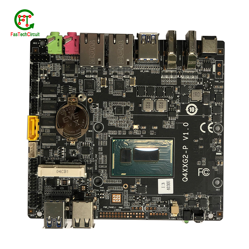
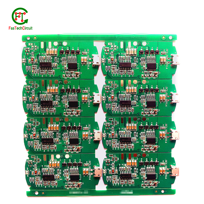
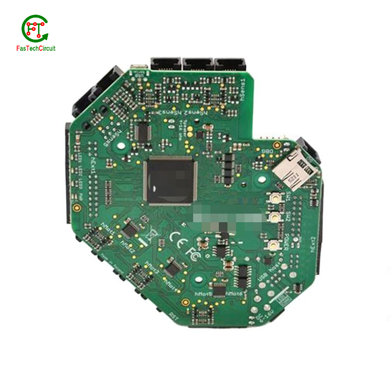
100w amplifier circuit pcb bearings FAQs Guide Welcome to our state-of-the-art PCB (Printed Circuit Board) products. We are proud to offer a comprehensive range of high-quality and versatile PCB solutions to meet the constantly evolving needs of the modern electronics industry.Our PCBs are expertly designed and manufactured using the latest technology and advanced techniques, ensuring reliability, durability, and exceptional performance for a wide range of applications. We understand the importance of precision and attention to detail in the production of PCBs and we are committed to meeting stringent quality standards.
2.What is the process of etching a 100w amplifier circuit pcb?
3.What is the role of silkscreen on a 100w amplifier circuit pcb?
4.Can 100w amplifier circuit pcbs be used for high-speed data transmission?
5.Can a 100w amplifier circuit pcb be used with both through-hole and surface mount components?
6.What is the difference between a gold-plated and a tin-plated 100w amplifier circuit pcb?
7.How are 100w amplifier circuit pcbs protected from environmental factors?
8.Can 100w amplifier circuit pcbs be used for high-temperature applications?
9.What is the purpose of a ground plane on a 100w amplifier circuit pcb?
10.What is the purpose of a solder mask on a 100w amplifier circuit pcb?
11.Can a 100w amplifier circuit pcb be used for both power and signal transmission?
12.How are 100w amplifier circuit pcbs protected from moisture and humidity?
13.What is the difference between single-sided, double-sided, and multi-layer 100w amplifier circuit pcb?
14.How are high-speed/high-frequency 100w amplifier circuit pcb tested and validated?
15.What is the role of vias on a 100w amplifier circuit pcb?
1.What are the main components of a 100w amplifier circuit pcb?
We continuously upgrade our skills and knowledge to adapt to changing 100w amplifier circuit pcb market needs.
A typical PCB consists of several vital components, including a substrate material, copper traces, solder mask, silk screen, and plated through-holes. The substrate material acts as the base and provides mechanical support for the board. Copper traces, usually made of thin lines of copper foil, serve as the conductive paths for transmitting electrical signals. The solder mask, applied as a protective layer, prevents accidental short circuits and corrosion. Silk screen, a layer of ink-based labeling, aids in component identification. Lastly, plated through-holes enable electrical connection between different layers of the PCB board. These components work together to form a fully functioning PCB.
2.What is the process of etching a 100w amplifier circuit pcb?
We have flexible production capacity. Whether you are large orders or small orders, you can produce and release goods in a timely manner to meet customer needs.
PCB (Printed Circuit Board) etching is the process of creating a circuit pattern on a copper-clad board by using chemical etchants to selectively remove the unwanted copper. The process begins by transferring the circuit design onto a copper-clad board using various methods such as printing or photolithography. Next, the board is coated with a resist material, which protects the areas of copper that will eventually become the circuit traces. The board is then placed in an etching solution, typically a mixture of acid and water, which dissolves the unprotected copper. Once the desired circuit pattern is etched into the board, the resist material is removed, and the board is cleaned and inspected for any imperfections. PCB etching is a crucial step in the manufacturing of PCBs, as it creates the necessary conductive pathways for electronic components to be mounted and interconnected, making it an essential process in the production of electronic devices.
3.What is the role of silkscreen on a 100w amplifier circuit pcb?
Being one of the top 100w amplifier circuit pcb manufacturers in China, We attach great importance to this detail.
Silkscreen, also known as legend or nomenclature, is a vital component of a printed circuit board (PCB). It is the layer of text and symbols that are printed on the surface of the PCB to provide essential information for component placement and identification. The silkscreen plays a crucial role in the manufacturing process of PCBs, as it helps to ensure the accuracy and functionality of the final product. By indicating component locations, values, and reference designators, the silkscreen serves as a guide for the assembly and soldering of electronic components. Additionally, it also provides important information for maintenance and troubleshooting purposes.
4.Can 100w amplifier circuit pcbs be used for high-speed data transmission?
Yes, PCBs (printed circuit boards) can be used for high-speed data transmission. PCBs are commonly used in electronic devices and systems to connect and route electrical signals between components. They are designed to have specific trace widths, lengths, and impedance to ensure efficient and reliable transmission of high-speed signals. Additionally, PCBs can be designed with specialized materials and techniques, such as controlled impedance and differential signaling, to further optimize their performance for high-speed data transmission.
5.Can a 100w amplifier circuit pcb be used with both through-hole and surface mount components?
We continue to improve 100w amplifier circuit pcb products and processes to improve efficiency.
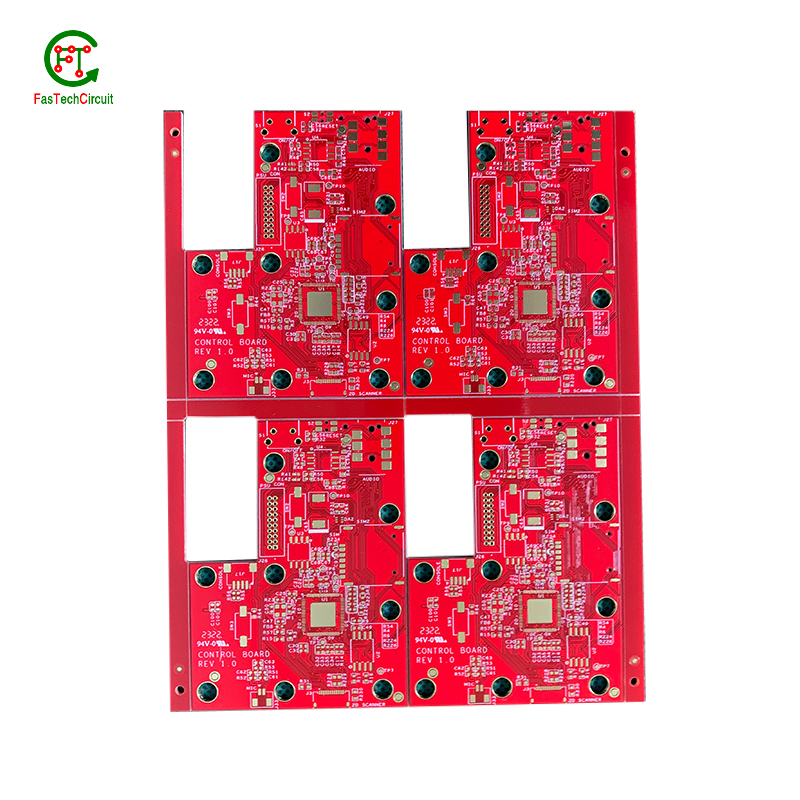
Yes, a PCB (printed circuit board) can be designed to accommodate both through-hole and surface mount components. This is known as a mixed-technology PCB. The PCB will have both through-hole and surface mount pads and traces, allowing for the placement and soldering of both types of components. This type of PCB is commonly used in electronic devices that require a combination of through-hole and surface mount components for functionality.
6.What is the difference between a gold-plated and a tin-plated 100w amplifier circuit pcb?
A gold-plated PCB (Printed Circuit Board) is a type of PCB that has a thin layer of gold coating on its surface. This layer is added through a process called electroplating and is commonly used to protect the PCB components from corrosion and increase the conductivity. On the other hand, a tin-plated PCB has a layer of tin coating on its surface, which is also applied through electroplating. Unlike gold plating, tin plating is mainly used to prevent oxidization and improve solderability.
7.How are 100w amplifier circuit pcbs protected from environmental factors?
We have established long-term and stable partnerships with our suppliers, so we have great advantages in price and cost and quality assurance.
PCBs, or printed circuit boards, are protected from environmental factors through the use of various techniques and materials. One method is to coat the PCB with a layer of conformal coating, which is a thin layer of protective material that covers the components and circuitry on the board. This coating can protect the PCB from moisture, dust, and other contaminants that could cause damage.
In addition to conformal coating, PCBs can also be protected through designing the layout of the board in a way that minimizes exposure to environmental factors. This includes placing sensitive components in areas that are less susceptible to moisture or temperature changes, as well as using specialized materials that are resistant to the effects of heat, humidity, and other environmental conditions.
8.Can 100w amplifier circuit pcbs be used for high-temperature applications?
Yes, PCBs (printed circuit boards) can be used for high-temperature applications. However, the materials and design of the PCB must be carefully chosen to ensure that it can withstand the high temperatures without degrading or malfunctioning.
Some factors to consider when using PCBs for high-temperature applications include the type of substrate material, the type of solder used, and the thickness of the copper traces. High-temperature substrates such as ceramic or polyimide can withstand temperatures up to 300°C, while standard FR4 substrates are only suitable for temperatures up to 130°C.
Specialized solder materials, such as high-temperature lead-free solders, may also be necessary to ensure the reliability of the PCB at high temperatures. Additionally, thicker copper traces can help dissipate heat more effectively and prevent damage to the PCB.
9.What is the purpose of a ground plane on a 100w amplifier circuit pcb?
I have a comprehensive after -sales service system, which can pay attention to market trends in time and adjust our strategy in a timely manner.
A decoupling capacitor is an essential component on a PCB (Printed Circuit Board) which is used to reduce or eliminate high frequency noise between different components. It acts as a buffer between the power supply and other circuit components, by storing electrical charge and then releasing it when there is a sudden change in the supply voltage. This helps to stabilize the power supply, providing a steady and noise-free flow of electricity to the circuit. Furthermore, decoupling capacitors also help to filter out any unwanted signals that may cause interference or disruptions in the proper functioning of the circuit.
10.What is the purpose of a solder mask on a 100w amplifier circuit pcb?
We have a good reputation and image in the industry. The quality and price advantage of 100w amplifier circuit pcb products is an important factor in our hard overseas market.
A solder mask is a thin layer of protective material applied to a printed circuit board (PCB) to prevent solder from bridging between conductive traces, pads, or vias during the soldering process. It also helps to protect the PCB from environmental factors such as moisture, dust, and corrosion. Additionally, the solder mask can provide insulation between conductive traces, reducing the risk of short circuits. It also helps to improve the overall appearance of the PCB by providing a uniform and professional finish.
11.Can a 100w amplifier circuit pcb be used for both power and signal transmission?
Yes, a PCB (printed circuit board) can be used for both power and signal transmission. This is commonly seen in electronic devices such as computers, smartphones, and other electronic devices. The PCB acts as a platform for connecting various components and circuits, including power sources and signal pathways. The power and signal traces on the PCB are designed to handle different levels of current and voltage to ensure efficient transmission and prevent interference between the two. However, it is important to properly design and layout the PCB to ensure proper separation and isolation of power and signal traces to avoid any potential issues.
12.How are 100w amplifier circuit pcbs protected from moisture and humidity?
PCB (Printed Circuit Boards) are susceptible to damage from moisture and humidity, which can result in malfunction or even complete failure of electronic devices. Therefore, it is necessary to take measures to protect PCBs from these elements.
One way to protect PCBs from moisture is by using a conformal coating. This is a thin layer of protective material that is applied to the surface of the PCB. It acts as a barrier, preventing moisture from coming into contact with the sensitive components on the board.
Another method is to use moisture-resistant materials for the PCB itself. This can include using moisture-resistant coatings or laminates for the board, as well as corrosion-resistant materials for the conductors and connectors.
In addition to these preventive measures, PCBs can also be stored in controlled environments with low humidity levels. This can help to minimize the amount of moisture that comes into contact with the boards, reducing the risk of damage.
Regular maintenance and periodic testing can also help to ensure the continued protection of PCBs from moisture and humidity. By taking these precautions, electronic devices can maintain their functionality and reliability, even in environments with high humidity levels.
13.What is the difference between single-sided, double-sided, and multi-layer 100w amplifier circuit pcb?
We have established a good reputation and reliable partnerships within the 100w amplifier circuit pcb industry.
Single-sided PCB (Printed Circuit Board) is a type of PCB that has components and traces on only one side of the board. The other side is usually used for soldering and mounting the board onto a larger circuit.
Double-sided PCB is a type of PCB that has components and traces on both sides of the board. The traces on both sides are connected through vias, which are small holes drilled through the board and plated with metal to create an electrical connection.
Multi-layer PCB is a type of PCB that has multiple layers of conductive material and insulating material sandwiched together. The layers are connected through vias, allowing for more complex and compact circuit designs. Multi-layer PCBs are used in more advanced and high-performance electronic devices.
14.How are high-speed/high-frequency 100w amplifier circuit pcb tested and validated?
Testing and validation are essential steps in the production process of high-speed and high-frequency printed circuit boards (PCBs). These specialized types of PCBs are used in a wide range of industries, including telecommunications, aerospace, and automotive, and require precision and reliability in their performance.
The testing and validation process for high-speed/high-frequency PCBs involves several steps to ensure that the final product meets the required specifications. This starts with design simulation and analysis using specialized software to verify the layout and electrical characteristics of the PCB.
Once the design is confirmed, prototype PCBs are manufactured and subjected to various tests, including signal integrity and power integrity tests. These tests evaluate the electrical performance of the PCB, such as its ability to transmit signals at high speeds and maintain signal integrity.
In addition to electrical tests, environmental and mechanical tests are also performed to assess the durability and reliability of the PCB under different conditions, such as temperature changes and mechanical stress.
The final step in the testing and validation process is the inspection and analysis of the tested PCBs. This involves a detailed review of the test results and any necessary modifications to meet the required specifications.
15.What is the role of vias on a 100w amplifier circuit pcb?
Our company has many years of 100w amplifier circuit pcb experience and expertise.
Vias play a crucial role in connecting different layers of a printed circuit board (PCB). These small, plated holes act as conductive paths, allowing signals and power to pass through the board and reach various components. Vias are also essential for routing traces from one layer to another, optimizing the layout and reducing the size and complexity of the board. Additionally, vias provide structural support and improve thermal management by facilitating heat dissipation.
RELATED PRODUCTS & SERVICE
pcb board manufacturing How To Contact US
PCB from 1 to 30 layers, HDI, Heavy Copper, Rigid-flex board with "pcb board manufacturing One-Stop" service.

