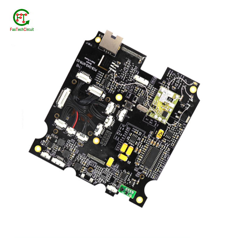
2675-00928 main pcb board
We built a factory in Shenzhen; our factory's designed production capacity can reach up to 25,000 square meters per month. We purchase and assemble the most advanced production equipment from China, Germany, Japan to ensure the best quality of our PCBs; We have ISO-9001 quality system certification and ISO-14001 environmental system certification. All of our PCBs are UL certified. Fast response, strict quality control, best service, strong technical support and effective improvement enable HFasTechCircuit to export our PCB products to the global market, which are widely used in the telecommunications industry, automobile industry, computer, home appliance industry, and Large LED equipment; we can provide one-stop OEM service, price advantage, and fast delivery! Our products are very popular in Mongolia,Paraguay,Vietnam,Haiti,French Guiana, the United States and Japan. Won high praise from customers.
| Model Number | customized PCBA |
| Type | pcba |
| Place of Origin | Guangdong, China |
| Brand Name | none |
| Copper Thickness | 1 oz |
| Supplier Type | OEM |
| Application | Electronics Device |
| Service | One-step Service |
| Layer | 1-38layers |
| Solder mask color | Blue.green.red.black.white.etc |
| Testing Service | 100% |
| Component size | 0201-1165mm |
| Component max height | 25mm |
| Min lead pitch | 0.4mm |
| Min BGA ball pitch | 0.3mm |
| Max PCB size | 501x463mm |
| Packaging Details | Vacuum package for bare PCB and ESD package for PCBA Printed Circuit Board Factory FPC Board PCBA Companies PCBA Assembly |
| Supply Ability | 54047 Piece/Pieces per Week |
| Quantity (pieces) | > 854 |
| Lead time (days) | 9 |
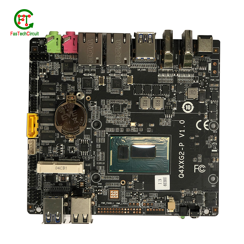
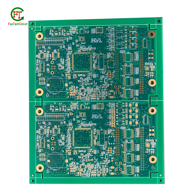
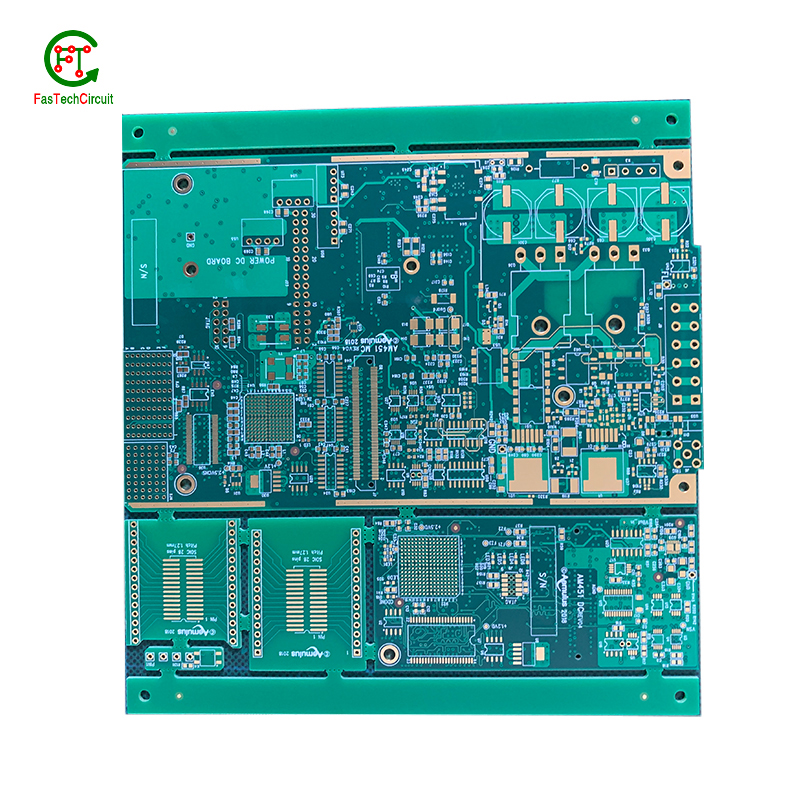
2675-00928 main pcb board bearings FAQs Guide Welcome to our state-of-the-art PCB (Printed Circuit Board) products. We are proud to offer a comprehensive range of high-quality and versatile PCB solutions to meet the constantly evolving needs of the modern electronics industry.Our PCBs are expertly designed and manufactured using the latest technology and advanced techniques, ensuring reliability, durability, and exceptional performance for a wide range of applications. We understand the importance of precision and attention to detail in the production of PCBs and we are committed to meeting stringent quality standards.
2.How are signal integrity issues addressed in 2675-00928 main pcb board design?
3.How are components attached to a 2675-00928 main pcb board?
4.What software is used for 2675-00928 main pcb board design?
5.What is the role of a data sheet in 2675-00928 main pcb board design?
6.What type of solder is used for 2675-00928 main pcb board assembly?
7.How are through-hole components soldered onto a 2675-00928 main pcb board?
8.Can 2675-00928 main pcb boards be used for high-speed data transmission?
9.How are power and ground planes connected on a 2675-00928 main pcb board?
10.How are 2675-00928 main pcb boards designed?
11.What is the role of automated optical inspection (AOI) in 2675-00928 main pcb board production?
12.How are holes drilled into a 2675-00928 main pcb board?
13.What types of 2675-00928 main pcb boards are there?
14.How are 2675-00928 main pcb board used in medical devices?
1.How are components selected for a 2675-00928 main pcb board design?
We pay attention to employee development and benefits, and provide a good working environment in order to improve the efficiency of employees and improve the quality management of 2675-00928 main pcb board products.
A power rating for a PCB, or Printed Circuit Board, is a measure of the maximum amount of power the board is able to safely handle. This rating takes into account the overall design and materials used in the creation of the PCB, as well as the environment in which it will be used. It is an important consideration in electronics and circuit design as exceeding the power rating can lead to overheating and potential damage to the board and connected components. Properly understanding and adhering to the power rating of a PCB is crucial for ensuring safe and efficient operation of electronic devices.
2.How are signal integrity issues addressed in 2675-00928 main pcb board design?
We focus on our customers' needs and strive to meet their expectations, so we take this very seriously.
Signal integrity issues are a common concern in PCB design, as they can greatly affect the performance and reliability of electronic systems. These issues arise from high-speed signal transmissions on the board, which can result in degraded signals, data errors, and even system failures. In order to address these issues, PCB designers must consider various factors such as layout, routing, and component placement to ensure proper signal integrity. This involves implementing signal protection measures such as controlled impedance routing, signal shielding, and minimizing signal crosstalk. Additionally, designers may use simulation and analysis tools to identify and resolve any potential signal integrity problems before the PCB goes into production. By carefully addressing signal integrity issues in the design phase, PCBs can achieve optimal performance and functionality.
3.How are components attached to a 2675-00928 main pcb board?
We adhere to the principle of integrity and transparency, and establish long -term relationships with partners, and we attach great importance to this detail.
eads or pins of the component and melting solder onto them, whicComponents are attached to a PCB (printed circuit board) through a process called soldering. This involves heating the metal lh then solidifies and creates a strong electrical and mechanical connection between the component and the PCB. There are two main methods of soldering components onto a PCB:
1. Through-hole soldering: This method involves inserting the leads or pins of the component through pre-drilled holes on the PCB and soldering them on the opposite side of the board. This method is commonly used for larger components such as resistors, capacitors, and integrated circuits.
2. Surface mount soldering: This method involves soldering the component directly onto the surface of the PCB, without the need for pre-drilled holes. This is done using specialized equipment such as a soldering iron or a reflow oven. Surface mount components are smaller in size and are commonly used for more complex and compact electronic devices.
4.What software is used for 2675-00928 main pcb board design?
Our 2675-00928 main pcb board products have competitive and differentiated advantages, and actively promote digital transformation and innovation.
Some popular software used for PCB design include:
1. Altium Designer
2. Eagle PCB
3. KiCad
4. OrCAD
5. PADS
6. Proteus
7. DipTrace
8. EasyEDA
9. CircuitMaker
10. DesignSpark PCB
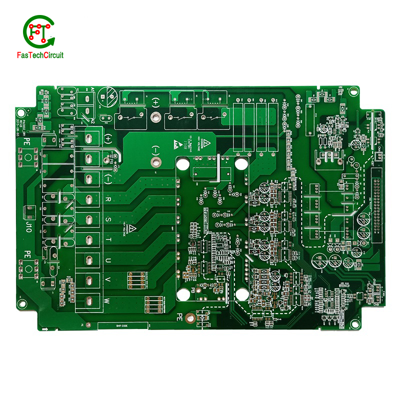
5.What is the role of a data sheet in 2675-00928 main pcb board design?
A data sheet is an essential tool for PCB design, providing vital information and specifications for all of the components used in the design process. It contains detailed technical data, such as dimensions, electrical ratings, and performance characteristics, that allow designers to make informed decisions when selecting and placing components on a PCB. By referencing the data sheet, designers can ensure that each component is properly integrated into the overall design, following any necessary guidelines or restrictions. Additionally, data sheets also provide necessary information for the layout and routing of traces on the PCB, ensuring that the design can meet required performance specifications.
6.What type of solder is used for 2675-00928 main pcb board assembly?
The most commonly used solder for PCB assembly is a lead-free solder, specifically a tin-silver-copper (SnAgCu) alloy. This type of solder is preferred due to its high melting point, good wetting properties, and compatibility with surface mount technology (SMT) components. Other types of solder that may be used include tin-lead (SnPb) solder and lead-free alternatives such as tin-copper (SnCu) and tin-bismuth (SnBi) alloys. The specific type of solder used may vary depending on the application and industry standards.
7.How are through-hole components soldered onto a 2675-00928 main pcb board?
Through-hole components are soldered onto a printed circuit board (PCB) using a process called wave soldering. First, the PCB is fitted with all the necessary through-hole components, such as resistors, capacitors, and diodes. Then, the board is passed over a wave of molten solder, which flows through the holes in the PCB and creates a secure connection between the component and the board. The excess solder is removed and the board is inspected to ensure all components are properly soldered. This method of soldering provides a strong and reliable connection for through-hole components, making it a popular choice for electronic assembly.
8.Can 2675-00928 main pcb boards be used for high-speed data transmission?
Yes, PCBs (printed circuit boards) can be used for high-speed data transmission. PCBs are commonly used in electronic devices and systems to connect and route electrical signals between components. They are designed to have specific trace widths, lengths, and impedance to ensure efficient and reliable transmission of high-speed signals. Additionally, PCBs can be designed with specialized materials and techniques, such as controlled impedance and differential signaling, to further optimize their performance for high-speed data transmission.
9.How are power and ground planes connected on a 2675-00928 main pcb board?
Power and ground planes are typically connected on a PCB through vias, which are small holes drilled through the layers of the PCB. These vias are filled with conductive material, such as copper, and allow for the flow of current between the power and ground planes. The vias are strategically placed throughout the PCB to ensure a low impedance connection between the power and ground planes. Additionally, traces or copper pours can also be used to connect the power and ground planes on different layers of the PCB.
10.How are 2675-00928 main pcb boards designed?
We should perform well in market competition, and the prices of 2675-00928 main pcb board products have a great competitive advantage.
Printed Circuit Boards, commonly known as PCBs, are an essential part of modern-day technology. They serve as the foundation for electronic devices and are crucial to their functionality. The process of designing a PCB involves several stages, starting with creating a schematic diagram that outlines the connections between various electronic components. This is followed by placement and routing, where the physical layout of the board is determined and traces are added to connect the components. PCB designers use advanced software to optimize the layout and ensure that it meets the necessary electrical and mechanical requirements. Once the design is finalized, manufacturers can use the design files to produce the PCB. Designing a PCB requires a combination of technical knowledge, creativity, and attention to detail to create a functional and efficient circuit board for a specific application.
11.What is the role of automated optical inspection (AOI) in 2675-00928 main pcb board production?
Automated optical inspection (AOI) plays a crucial role in the production of printed circuit boards (PCBs). It is a technology that uses advanced imaging techniques to detect and identify defects or errors on a PCB, such as missing components, incorrect placement, and faulty soldering. AOI has become an essential step in the production process as it helps manufacturers ensure the quality and reliability of their PCBs. By detecting and identifying defects at an early stage, AOI can significantly reduce the number of defects and increase the efficiency of the production process. Furthermore, AOI is able to perform inspections at a much faster rate and with higher accuracy compared to manual inspection, making it an indispensable tool for PCB production.
12.How are holes drilled into a 2675-00928 main pcb board?
We actively participate in the 2675-00928 main pcb board industry associations and organization activities. The corporate social responsibility performed well, and the focus of brand building and promotion.
Drilling holes into printed circuit boards (PCBs) is a critical part of the PCB manufacturing process. These holes are used for mounting electronic components and for creating electrical connections between different layers of the board. There are two main methods for drilling holes into a PCB – mechanical drilling and laser drilling. Mechanical drilling involves using a high speed drill bit to physically drill through the board, while laser drilling uses a high-powered laser to vaporize the material and create the holes. Both methods have their own advantages and are often used in combination to achieve the desired hole sizes and precision. Regardless of the method, the holes are carefully planned and executed to ensure the successful production of a high-quality PCB.
13.What types of 2675-00928 main pcb boards are there?
As one of the 2675-00928 main pcb board market leaders, we are known for innovation and reliability.
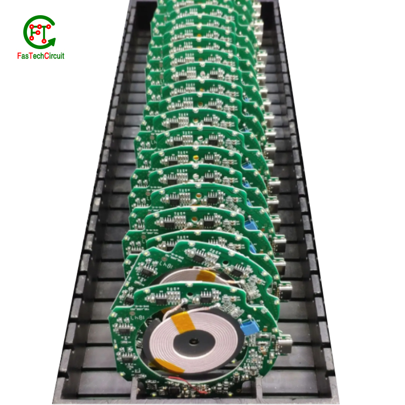
There are several types of PCBs, including single-sided, double-sided, multi-layer, and flexible PCBs. Single-sided PCBs have components mounted on one side and conductive traces on the other. Double-sided PCBs have components mounted on both sides with conductive traces connecting them. Multi-layer PCBs have several layers of conductive traces and insulating material sandwiched together. Flexible PCBs are made from a flexible plastic material, allowing them to bend and twist for use in applications where traditional rigid PCBs are not suitable. Each type of PCB serves a different purpose and can be used in a variety of electronic devices and applications.
14.How are 2675-00928 main pcb board used in medical devices?
Printed Circuit Boards (PCBs) are essential components used in a wide range of medical devices, playing a crucial role in both diagnostic and treatment equipment. These devices require reliable and precise circuitry to accurately collect and process data, deliver therapies, and regulate medical procedures. PCBs are used in equipment such as MRI machines, pacemakers, defibrillators, and monitors, where their small size and high density make them ideal for compact and portable designs. In addition, PCBs are also used in medical implants, enabling a safe and secure connection between the device and the body. With their advanced technology, PCBs continue to be an integral part of the medical industry, ensuring the effectiveness and success of various medical procedures and treatments.
RELATED PRODUCTS & SERVICE
pcb board manufacturing How To Contact US
PCB from 1 to 30 layers, HDI, Heavy Copper, Rigid-flex board with "pcb board manufacturing One-Stop" service.

