4 layer rf pcb design
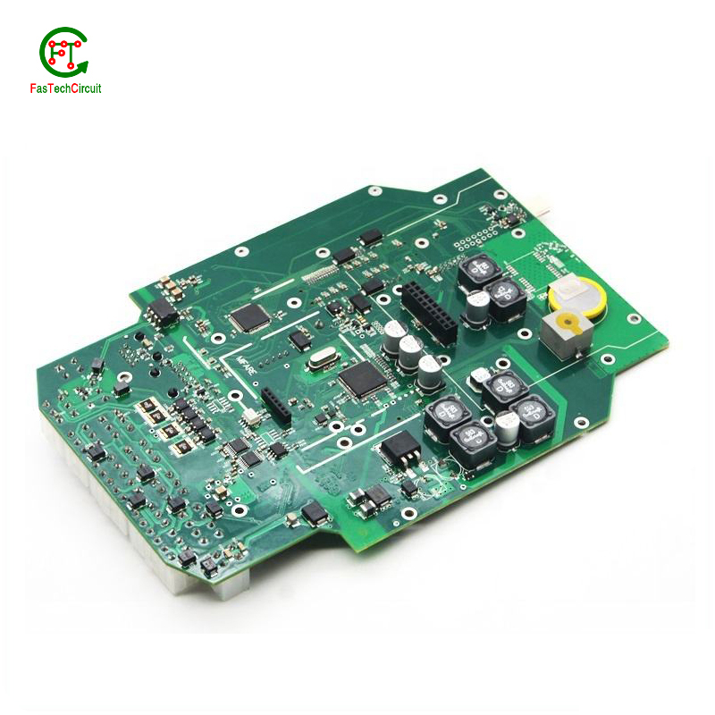
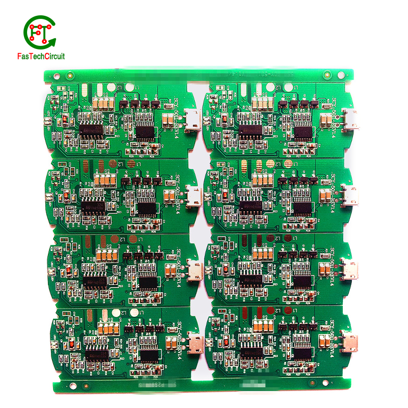
FasTechCircuit's products cover single-panel, double-panel, multi-layer boards, rigid boards, flexible boards, hybrid (rigid-soft) boards and other types. According to customer needs and application fields, we can provide PCB products of different materials and processes, such as FR-4, aluminum substrates, ceramic substrates, etc. At the same time, we can also provide a variety of surface treatment processes according to customer needs, such as OSP, HASL, ENIG, etc., to ensure the reliability and stability of the circuit board. We also provide non-standard customization services and can customize production according to the special requirements provided by customers to meet their personalized needs.
FasTechCircuit's printed circuit board products are widely used in communication equipment, industrial control, consumer electronics, computers and peripheral equipment, medical equipment, aerospace and other fields. Our products undergo strict quality control, have high precision, high reliability and stability, and can meet customers' high requirements for electronic products. Our products are very popular in Chad,Thailand,Togo,Kazakhstan,Namibia, the United States and Japan. Won high praise from customers.
| Number of Layers | 4 layer |
| Base Material | gold sinking |
| Board Thickness | 2.1MM |
| Board Size | 329M*593MM |
| Model Number | 4 layer pcb |
| Type | pcb |
| Place of Origin | Original |
| Brand Name | Original |
| Copper Thickness | 3OZ |
| Min. Hole Size | custom made |
| Min. Line Width | custom made |
| Min. Line Spacing | custom made |
| Surface Finishing | custom made |
| Impedance control | +/- 9% |
| Warpage | less than 1% |
| Packaging Details | New and Original, factory sealed packing, it will be pack in one of these packing type: Tube, Tray, Tape and Reel, Tape and Box, Bulk packing, Bag and etc. Please kindly contact us for more details. |
| Supply Ability | 7638 Piece/Pieces per Week |
| Quantity (pieces) | > 11100 |
| Lead time (days) | 10 |
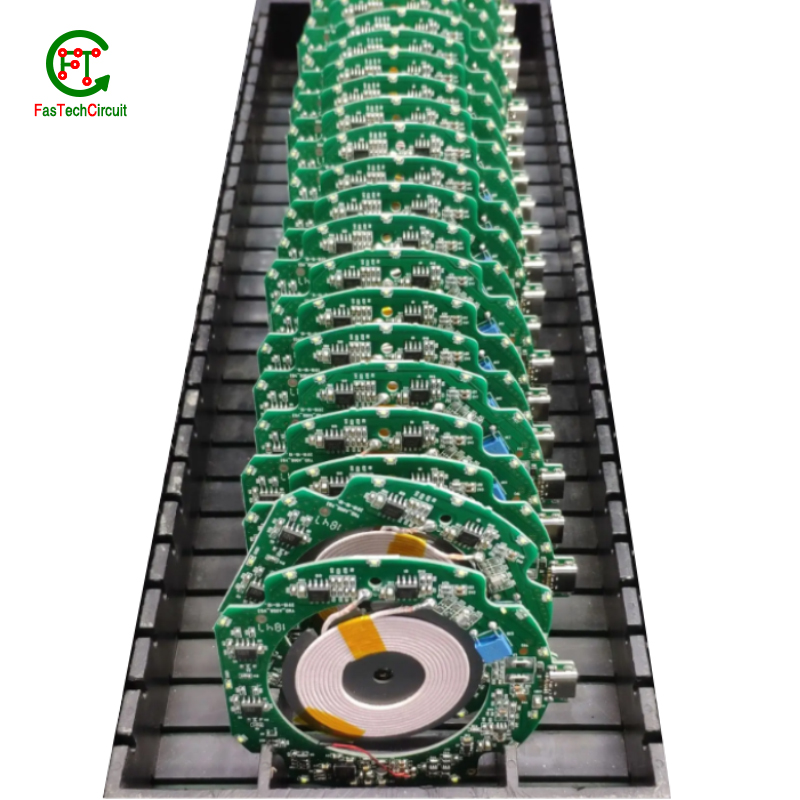
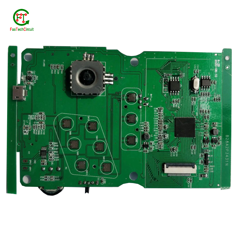
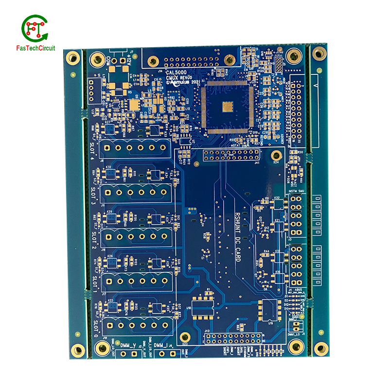
4 layer rf pcb design bearings FAQs Guide Welcome to our state-of-the-art PCB (Printed Circuit Board) products. We are proud to offer a comprehensive range of high-quality and versatile PCB solutions to meet the constantly evolving needs of the modern electronics industry.Our PCBs are expertly designed and manufactured using the latest technology and advanced techniques, ensuring reliability, durability, and exceptional performance for a wide range of applications. We understand the importance of precision and attention to detail in the production of PCBs and we are committed to meeting stringent quality standards.
2.What is the minimum thickness of a 4 layer rf pcb design?
3.What software is used for 4 layer rf pcb design design?
4.How are 4 layer rf pcb design used in medical devices?
5.What is the difference between an analog and a digital signal on a 4 layer rf pcb design?
6.What is the role of vias on a 4 layer rf pcb design?
7.What is a 4 layer rf pcb design?
8.What types of 4 layer rf pcb designs are there?
9.What is the function of a resistor on a 4 layer rf pcb design?
10.How are components attached to a 4 layer rf pcb design?
11.What is the purpose of a ground plane on a 4 layer rf pcb design?
12.What is the future outlook for 4 layer rf pcb design technology?
13.What is the maximum operating temperature of a 4 layer rf pcb design?
14.What is the purpose of a 4 layer rf pcb design?
15.How are 4 layer rf pcb designs tested for quality control?
16.Can 4 layer rf pcb designs be used for high-speed data transmission?
17.What is the lifespan of a 4 layer rf pcb design under harsh environmental conditions?
18.What is the purpose of a solder mask on a 4 layer rf pcb design?
1.What is the function of a decoupling capacitor on a 4 layer rf pcb design?
We have rich industry experience and professional knowledge, and have strong competitiveness in the market.
A decoupling capacitor is a type of capacitor that is used to reduce or eliminate noise and interference in electronic circuits. It is typically placed on a PCB (printed circuit board) near the power supply pins of an integrated circuit (IC) or other active component.
The main function of a decoupling capacitor is to provide a stable and clean power supply to the IC or other active component. This is achieved by filtering out high-frequency noise and voltage fluctuations that can be caused by other components on the PCB or external sources.
In addition, a decoupling capacitor also helps to prevent voltage drops and spikes that can occur when the IC or other component suddenly draws a large amount of current. This is especially important for sensitive components that require a stable power supply to function properly.
2.What is the minimum thickness of a 4 layer rf pcb design?
We are committed to providing personalized solutions and established long -term strategic cooperative relationships with customers.
The minimum thickness of a PCB (printed circuit board) can vary depending on the materials and manufacturing processes used. However, the standard minimum thickness for a single-sided PCB is 0.6mm (0.024 inches) and for a double-sided PCB it is 0.8mm (0.032 inches). Thinner PCBs can be made, but they may be more fragile and have limitations on the components and circuitry that can be used.
3.What software is used for 4 layer rf pcb design design?
Our 4 layer rf pcb design products have competitive and differentiated advantages, and actively promote digital transformation and innovation.
Some popular software used for PCB design include:
1. Altium Designer
2. Eagle PCB
3. KiCad
4. OrCAD
5. PADS
6. Proteus
7. DipTrace
8. EasyEDA
9. CircuitMaker
10. DesignSpark PCB
4.How are 4 layer rf pcb design used in medical devices?
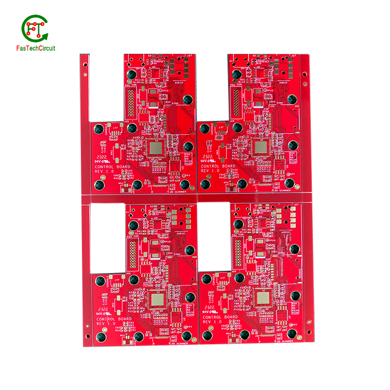
Printed Circuit Boards (PCBs) are essential components used in a wide range of medical devices, playing a crucial role in both diagnostic and treatment equipment. These devices require reliable and precise circuitry to accurately collect and process data, deliver therapies, and regulate medical procedures. PCBs are used in equipment such as MRI machines, pacemakers, defibrillators, and monitors, where their small size and high density make them ideal for compact and portable designs. In addition, PCBs are also used in medical implants, enabling a safe and secure connection between the device and the body. With their advanced technology, PCBs continue to be an integral part of the medical industry, ensuring the effectiveness and success of various medical procedures and treatments.
5.What is the difference between an analog and a digital signal on a 4 layer rf pcb design?
An analog signal is a continuous signal that varies in amplitude and frequency over time. It can take on any value within a given range and is typically represented by a smooth, continuous waveform. Analog signals are used to transmit information such as audio, video, and sensor data.
A digital signal, on the other hand, is a discrete signal that can only take on a limited number of values. It is represented by a series of binary digits (0s and 1s) and can only have two states: on or off. Digital signals are used to transmit information in the form of data and are commonly used in digital electronics such as computers and smartphones.
On a PCB, the main difference between analog and digital signals lies in the way they are processed and transmitted. Analog signals require specialized components such as amplifiers and filters to maintain their integrity, while digital signals can be processed and transmitted using digital logic circuits. Additionally, analog signals are more susceptible to noise and interference, while digital signals are more immune to these factors.
6.What is the role of vias on a 4 layer rf pcb design?
Our company has many years of 4 layer rf pcb design experience and expertise.
Vias play a crucial role in connecting different layers of a printed circuit board (PCB). These small, plated holes act as conductive paths, allowing signals and power to pass through the board and reach various components. Vias are also essential for routing traces from one layer to another, optimizing the layout and reducing the size and complexity of the board. Additionally, vias provide structural support and improve thermal management by facilitating heat dissipation.
7.What is a 4 layer rf pcb design?
We pay attention to user experience and product quality, and provide the best product quality and lowest production cost for cooperative customers.
A PCB (Printed Circuit Board) is a flat board made of non-conductive material, such as fiberglass, with conductive pathways etched or printed onto it. It is used to mechanically support and electrically connect electronic components using conductive tracks, pads, and other features etched from copper sheets laminated onto a non-conductive substrate. PCBs are commonly used in electronic devices such as computers, smartphones, and televisions to provide a platform for the components to be mounted and connected together. They are also used in a variety of other applications, including automotive, aerospace, and medical devices.
8.What types of 4 layer rf pcb designs are there?
As one of the 4 layer rf pcb design market leaders, we are known for innovation and reliability.
There are several types of PCBs, including single-sided, double-sided, multi-layer, and flexible PCBs. Single-sided PCBs have components mounted on one side and conductive traces on the other. Double-sided PCBs have components mounted on both sides with conductive traces connecting them. Multi-layer PCBs have several layers of conductive traces and insulating material sandwiched together. Flexible PCBs are made from a flexible plastic material, allowing them to bend and twist for use in applications where traditional rigid PCBs are not suitable. Each type of PCB serves a different purpose and can be used in a variety of electronic devices and applications.
9.What is the function of a resistor on a 4 layer rf pcb design?
We are a new 4 layer rf pcb design manufacturer.
The ground plane on a printed circuit board (PCB) serves as a reference point for the electrical signals that flow throughout the circuit. It is typically a large area of copper that is connected to the negative terminal of the power supply and serves as a low-impedance return path for current. Its main purpose is to provide a stable and uniform ground connection for the components on the PCB, helping to reduce electromagnetic interference and ensuring proper signal grounding. Without a ground plane, the circuit may experience noise and other unwanted effects, potentially causing malfunctions or disruptions in its functionality. Therefore, the ground plane plays a crucial role in ensuring the overall performance and reliability of a PCB.
10.How are components attached to a 4 layer rf pcb design?
We adhere to the principle of integrity and transparency, and establish long -term relationships with partners, and we attach great importance to this detail.
eads or pins of the component and melting solder onto them, whicComponents are attached to a PCB (printed circuit board) through a process called soldering. This involves heating the metal lh then solidifies and creates a strong electrical and mechanical connection between the component and the PCB. There are two main methods of soldering components onto a PCB:
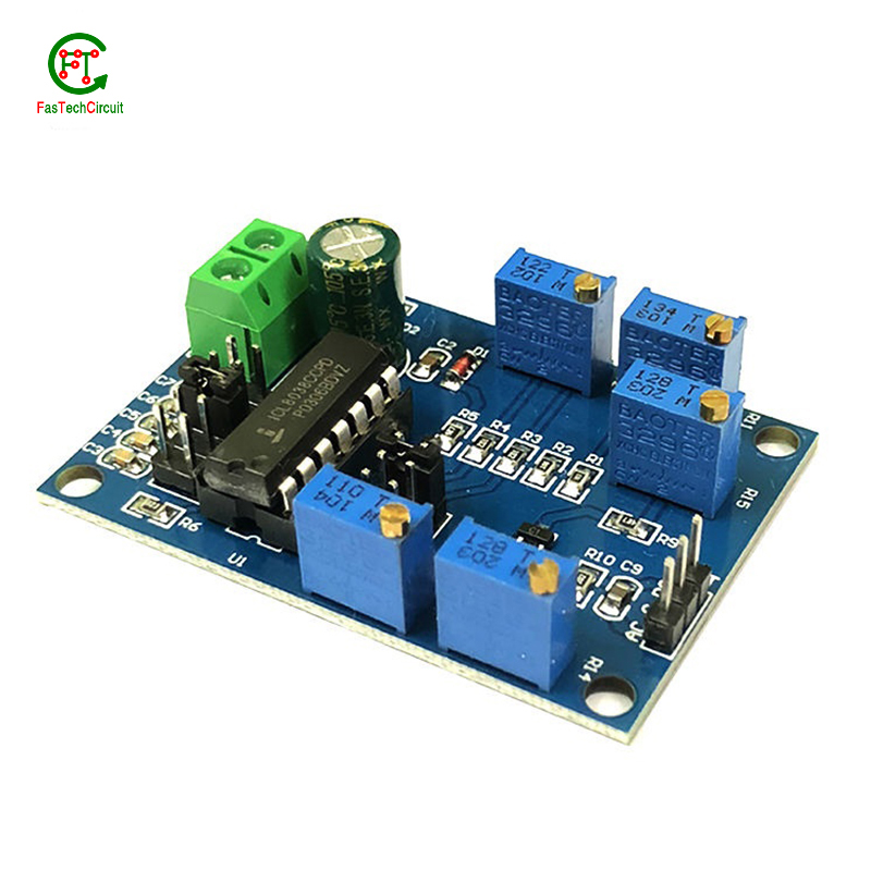
1. Through-hole soldering: This method involves inserting the leads or pins of the component through pre-drilled holes on the PCB and soldering them on the opposite side of the board. This method is commonly used for larger components such as resistors, capacitors, and integrated circuits.
2. Surface mount soldering: This method involves soldering the component directly onto the surface of the PCB, without the need for pre-drilled holes. This is done using specialized equipment such as a soldering iron or a reflow oven. Surface mount components are smaller in size and are commonly used for more complex and compact electronic devices.
11.What is the purpose of a ground plane on a 4 layer rf pcb design?
I have a comprehensive after -sales service system, which can pay attention to market trends in time and adjust our strategy in a timely manner.
A decoupling capacitor is an essential component on a PCB (Printed Circuit Board) which is used to reduce or eliminate high frequency noise between different components. It acts as a buffer between the power supply and other circuit components, by storing electrical charge and then releasing it when there is a sudden change in the supply voltage. This helps to stabilize the power supply, providing a steady and noise-free flow of electricity to the circuit. Furthermore, decoupling capacitors also help to filter out any unwanted signals that may cause interference or disruptions in the proper functioning of the circuit.
12.What is the future outlook for 4 layer rf pcb design technology?
Printed Circuit Boards, or PCBs, have been a vital component in electronic devices for decades. They serve as the foundation for the electrical connections and components that make our devices function properly. As technology continues to advance, so does the demand for smaller, faster, and more efficient PCBs. With the rise of IoT and smart devices, the future outlook for PCB technology is promising. It is expected that PCBs will become even more compact and complex, utilizing advanced materials and techniques such as 3D printing and flexible substrates. This will not only improve the performance of electronic devices, but also make them more durable and cost-effective. Furthermore, as sustainability becomes a growing concern, eco-friendly PCB materials and manufacturing processes are being developed to reduce environmental impact. With these advancements, it is safe to say that the future of PCB technology is bright and full of endless possibilities.
13.What is the maximum operating temperature of a 4 layer rf pcb design?
We have a professional team that is committed to the innovation and development of 4 layer rf pcb design.
The maximum operating temperature of a PCB (printed circuit board) can vary depending on the materials and components used in its construction. Generally, the maximum operating temperature for a standard FR4 PCB is around 130-140 degrees Celsius. However, specialized materials such as high-temperature laminates or ceramic substrates can withstand higher temperatures up to 200-250 degrees Celsius. The maximum operating temperature of a PCB should always be determined by the manufacturer's specifications and guidelines.
14.What is the purpose of a 4 layer rf pcb design?
We pay attention to the transformation of intellectual property protection and innovation achievements. Your OEM or ODM order design we have a complete confidentiality system.
A PCB (Printed Circuit Board) is a flat board made of non-conductive material, such as fiberglass, with conductive pathways etched or printed onto it. The main purpose of a PCB is to provide a platform for electronic components to be mounted and connected together to form a functioning electronic circuit. It serves as a physical support for the components and provides a means for them to communicate with each other through the conductive pathways. PCBs are used in a wide range of electronic devices, from simple household appliances to complex computer systems, and are essential for the proper functioning and reliability of these devices. They also allow for easier and more efficient production of electronic devices, as the components can be mounted and connected in a standardized and automated manner.
15.How are 4 layer rf pcb designs tested for quality control?
We have broad development space in domestic and foreign markets. 4 layer rf pcb design have great advantages in terms of price, quality, and delivery date.
PCB (Printed Circuit Board) testing is a critical step in the quality control process of electronic products. It ensures that all components and connections on the board are functioning correctly and that the PCB meets the required standards and specifications.
The testing process typically starts with a visual inspection to identify any visible defects, such as incorrect soldering or damaged components. Next, electrical testing is conducted to check the functionality of each individual component and the overall circuit.
One common method of testing is the use of a test fixture, which applies signals to the PCB and checks for correct responses. Other methods include automated optical inspection (AOI) and in-circuit testing (ICT).
Once the initial testing is completed, the PCB may undergo environmental testing to simulate real-life conditions and ensure its reliability and durability. This includes temperature and humidity cycling, vibration and shock testing, and more.
16.Can 4 layer rf pcb designs be used for high-speed data transmission?
Yes, PCBs (printed circuit boards) can be used for high-speed data transmission. PCBs are commonly used in electronic devices and systems to connect and route electrical signals between components. They are designed to have specific trace widths, lengths, and impedance to ensure efficient and reliable transmission of high-speed signals. Additionally, PCBs can be designed with specialized materials and techniques, such as controlled impedance and differential signaling, to further optimize their performance for high-speed data transmission.
17.What is the lifespan of a 4 layer rf pcb design under harsh environmental conditions?
The lifespan of a PCB (printed circuit board) under harsh environmental conditions can vary greatly depending on the specific conditions and the quality of the PCB. In general, a well-designed and high-quality PCB can last for 10-20 years under harsh conditions such as extreme temperatures, humidity, and exposure to chemicals or vibrations. However, if the PCB is not properly designed or manufactured, its lifespan can be significantly shorter, potentially lasting only a few years or even months. Factors such as the type of materials used, the thickness of the copper traces, and the quality of the solder joints can also affect the lifespan of a PCB under harsh environmental conditions. Regular maintenance and proper handling can also help extend the lifespan of a PCB.
18.What is the purpose of a solder mask on a 4 layer rf pcb design?
We have a good reputation and image in the industry. The quality and price advantage of 4 layer rf pcb design products is an important factor in our hard overseas market.
A solder mask is a thin layer of protective material applied to a printed circuit board (PCB) to prevent solder from bridging between conductive traces, pads, or vias during the soldering process. It also helps to protect the PCB from environmental factors such as moisture, dust, and corrosion. Additionally, the solder mask can provide insulation between conductive traces, reducing the risk of short circuits. It also helps to improve the overall appearance of the PCB by providing a uniform and professional finish.
RELATED PRODUCTS & SERVICE
pcb board manufacturing How To Contact US
PCB from 1 to 30 layers, HDI, Heavy Copper, Rigid-flex board with "pcb board manufacturing One-Stop" service.

