3 mm fr4 pcb board
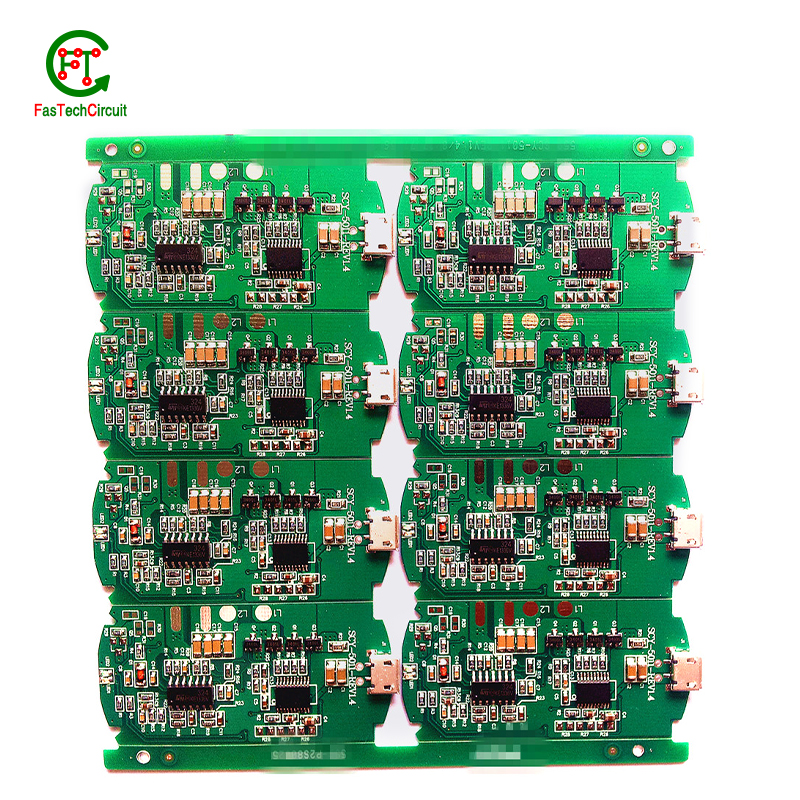
| Model Number | customized PCBA |
| Type | pcba |
| Place of Origin | Guangdong, China |
| Brand Name | none |
| Copper Thickness | 1 oz |
| Supplier Type | OEM |
| Application | Electronics Device |
| Service | One-step Service |
| Layer | 1-35layers |
| Solder mask color | Blue.green.red.black.white.etc |
| Testing Service | 100% |
| Component size | 0201-1127mm |
| Component max height | 30mm |
| Min lead pitch | 0.1mm |
| Min BGA ball pitch | 0.3mm |
| Max PCB size | 473x390mm |
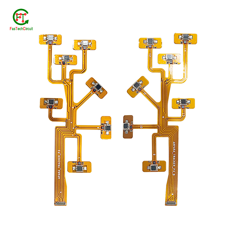
| Packaging Details | Vacuum package for bare PCB and ESD package for PCBA Printed Circuit Board Factory FPC Board PCBA Companies PCBA Assembly |
| Supply Ability | 48931 Piece/Pieces per Week |
| Quantity (pieces) | > 780 |
| Lead time (days) | 12 |
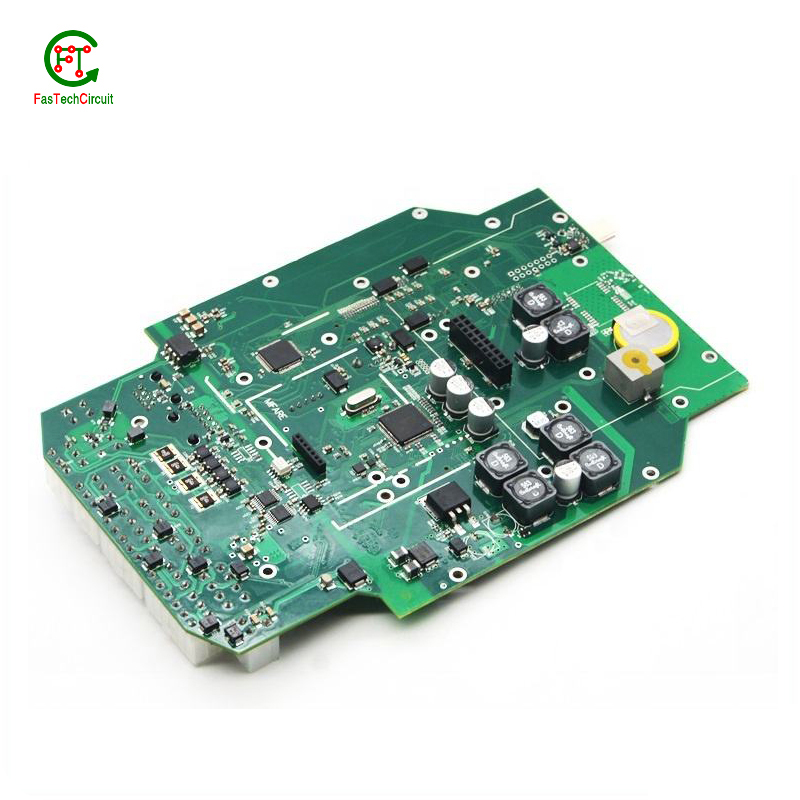
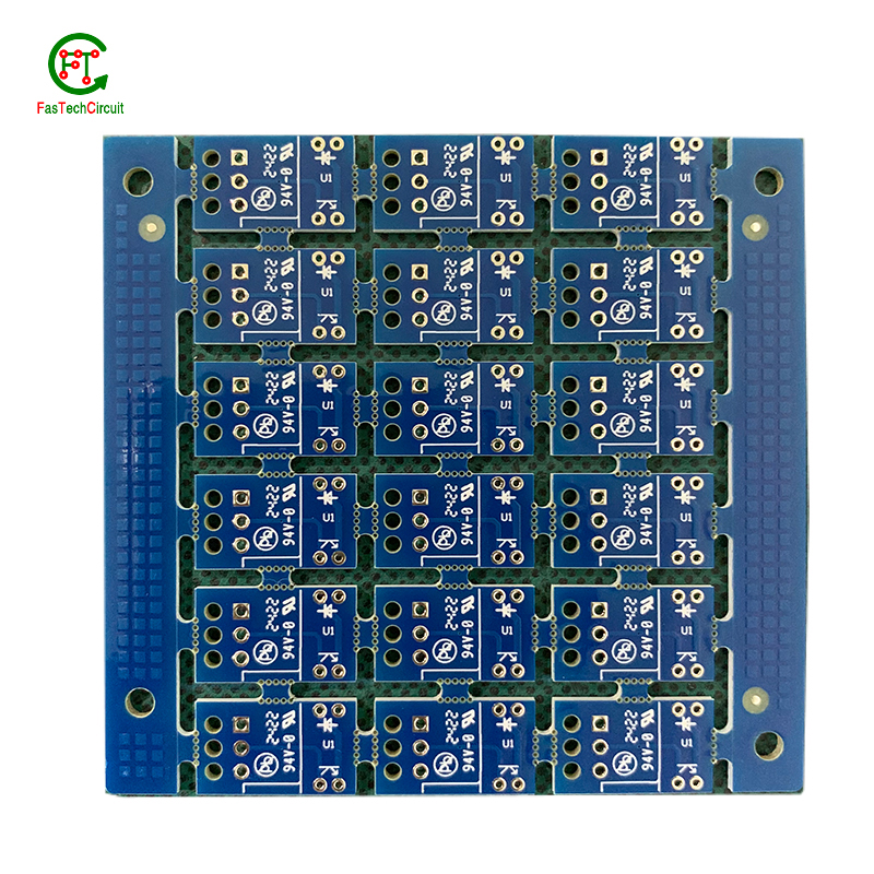
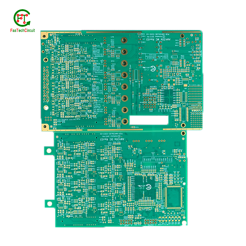
3 mm fr4 pcb board bearings FAQs Guide Welcome to our state-of-the-art PCB (Printed Circuit Board) products. We are proud to offer a comprehensive range of high-quality and versatile PCB solutions to meet the constantly evolving needs of the modern electronics industry.Our PCBs are expertly designed and manufactured using the latest technology and advanced techniques, ensuring reliability, durability, and exceptional performance for a wide range of applications. We understand the importance of precision and attention to detail in the production of PCBs and we are committed to meeting stringent quality standards.
2.How are 3 mm fr4 pcb boards protected from environmental factors?
3.What is the process of etching a 3 mm fr4 pcb board?
4.How are holes drilled into a 3 mm fr4 pcb board?
5.How are 3 mm fr4 pcb boards manufactured?
6.What are the benefits of using surface mount technology (SMT) for 3 mm fr4 pcb board?
7.Can a 3 mm fr4 pcb board be used with both through-hole and surface mount components?
8.How are components attached to a 3 mm fr4 pcb board?
9.Can a 3 mm fr4 pcb board be used for both power and signal transmission?
10.Are 3 mm fr4 pcb board recyclable?
11.How are high-frequency signals handled on a 3 mm fr4 pcb board?
12.What is the minimum trace width and spacing on a 3 mm fr4 pcb board?
13.Can 3 mm fr4 pcb boards be used in automotive applications?
14.What is noise coupling and how can it be prevented on a 3 mm fr4 pcb board?
15.Can 3 mm fr4 pcb boards be used in high-frequency applications?
16.How are 3 mm fr4 pcb board used in medical devices?
1.What is the difference between a copper pour and a trace on a 3 mm fr4 pcb board?
We adhere to the principle of quality first and have a complete production quality management system and quality inspection process.
A copper pour and a trace are two common electronic components that are found on a printed circuit board (PCB). A copper pour is a large area of copper that is used to connect multiple components or ground signals together on a PCB. This creates a solid and low resistance pathway for signals to flow. On the other hand, a trace is a thin line of copper used to connect individual components on a PCB. It carries a specific signal from one component to another. Unlike a copper pour, a trace can be designed to carry a specific current and have a specific width to meet the requirements of the circuit.
2.How are 3 mm fr4 pcb boards protected from environmental factors?
We have established long-term and stable partnerships with our suppliers, so we have great advantages in price and cost and quality assurance.
PCBs, or printed circuit boards, are protected from environmental factors through the use of various techniques and materials. One method is to coat the PCB with a layer of conformal coating, which is a thin layer of protective material that covers the components and circuitry on the board. This coating can protect the PCB from moisture, dust, and other contaminants that could cause damage.
In addition to conformal coating, PCBs can also be protected through designing the layout of the board in a way that minimizes exposure to environmental factors. This includes placing sensitive components in areas that are less susceptible to moisture or temperature changes, as well as using specialized materials that are resistant to the effects of heat, humidity, and other environmental conditions.
3.What is the process of etching a 3 mm fr4 pcb board?
We have flexible production capacity. Whether you are large orders or small orders, you can produce and release goods in a timely manner to meet customer needs.
PCB (Printed Circuit Board) etching is the process of creating a circuit pattern on a copper-clad board by using chemical etchants to selectively remove the unwanted copper. The process begins by transferring the circuit design onto a copper-clad board using various methods such as printing or photolithography. Next, the board is coated with a resist material, which protects the areas of copper that will eventually become the circuit traces. The board is then placed in an etching solution, typically a mixture of acid and water, which dissolves the unprotected copper. Once the desired circuit pattern is etched into the board, the resist material is removed, and the board is cleaned and inspected for any imperfections. PCB etching is a crucial step in the manufacturing of PCBs, as it creates the necessary conductive pathways for electronic components to be mounted and interconnected, making it an essential process in the production of electronic devices.
4.How are holes drilled into a 3 mm fr4 pcb board?
We actively participate in the 3 mm fr4 pcb board industry associations and organization activities. The corporate social responsibility performed well, and the focus of brand building and promotion.
Drilling holes into printed circuit boards (PCBs) is a critical part of the PCB manufacturing process. These holes are used for mounting electronic components and for creating electrical connections between different layers of the board. There are two main methods for drilling holes into a PCB – mechanical drilling and laser drilling. Mechanical drilling involves using a high speed drill bit to physically drill through the board, while laser drilling uses a high-powered laser to vaporize the material and create the holes. Both methods have their own advantages and are often used in combination to achieve the desired hole sizes and precision. Regardless of the method, the holes are carefully planned and executed to ensure the successful production of a high-quality PCB.
5.How are 3 mm fr4 pcb boards manufactured?
We have the leading technology and innovation capabilities, and attach importance to employee training and development, and provide promotion opportunities.
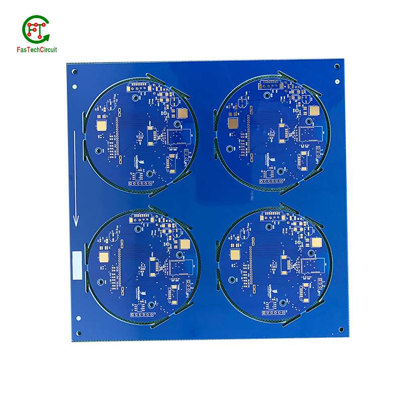
PCB are manufactured through a series of steps starting with designing the circuit layout. Once the design is finalized, the layout is printed on a special type of paper known as the “artwork”. This artwork is then transferred onto a copper-coated laminate board through a process called etching. The excess copper is removed, leaving behind the desired circuit pattern. The board is then drilled to create holes for components to be inserted. The next step involves adding a thin layer of solder mask to protect the circuit and adding a thin layer of copper to create traces. Finally, the components are added using a specialized machine, and the board goes through a series of tests to ensure proper functionality. Once the tests are passed, the board is cut and separated into individual PCBs for use in various electronic devices.
6.What are the benefits of using surface mount technology (SMT) for 3 mm fr4 pcb board?
We focus on innovation and continuous improvement to maintain a competitive advantage.
Surface mount technology (SMT) is a popular method for assembling printed circuit boards (PCBs) that offers numerous benefits over traditional through-hole components. Firstly, SMT components are smaller and more compact, allowing for greater PCB density and reducing the overall size of the board. This makes SMT ideal for increasingly miniaturized electronics, such as smartphones and wearables. Additionally, SMT components are typically cheaper and easier to manufacture, leading to cost savings in both materials and labor. SMT also allows for automated assembly, resulting in faster and more efficient production processes. Furthermore, the smaller size of SMT components leads to improved electrical performance due to decreased parasitic effects and shorter signal paths. This makes SMT ideal for high-frequency applications.
7.Can a 3 mm fr4 pcb board be used with both through-hole and surface mount components?
We continue to improve 3 mm fr4 pcb board products and processes to improve efficiency.
Yes, a PCB (printed circuit board) can be designed to accommodate both through-hole and surface mount components. This is known as a mixed-technology PCB. The PCB will have both through-hole and surface mount pads and traces, allowing for the placement and soldering of both types of components. This type of PCB is commonly used in electronic devices that require a combination of through-hole and surface mount components for functionality.
8.How are components attached to a 3 mm fr4 pcb board?
We adhere to the principle of integrity and transparency, and establish long -term relationships with partners, and we attach great importance to this detail.
eads or pins of the component and melting solder onto them, whicComponents are attached to a PCB (printed circuit board) through a process called soldering. This involves heating the metal lh then solidifies and creates a strong electrical and mechanical connection between the component and the PCB. There are two main methods of soldering components onto a PCB:
1. Through-hole soldering: This method involves inserting the leads or pins of the component through pre-drilled holes on the PCB and soldering them on the opposite side of the board. This method is commonly used for larger components such as resistors, capacitors, and integrated circuits.
2. Surface mount soldering: This method involves soldering the component directly onto the surface of the PCB, without the need for pre-drilled holes. This is done using specialized equipment such as a soldering iron or a reflow oven. Surface mount components are smaller in size and are commonly used for more complex and compact electronic devices.
9.Can a 3 mm fr4 pcb board be used for both power and signal transmission?
Yes, a PCB (printed circuit board) can be used for both power and signal transmission. This is commonly seen in electronic devices such as computers, smartphones, and other electronic devices. The PCB acts as a platform for connecting various components and circuits, including power sources and signal pathways. The power and signal traces on the PCB are designed to handle different levels of current and voltage to ensure efficient transmission and prevent interference between the two. However, it is important to properly design and layout the PCB to ensure proper separation and isolation of power and signal traces to avoid any potential issues.
10.Are 3 mm fr4 pcb board recyclable?
We have been working hard to improve service quality and meet customer needs.
Yes, PCBs (printed circuit boards) are recyclable. They can be broken down and the individual components can be reused or repurposed. However, the recycling process can be complex and requires specialized equipment and techniques. It is important to properly dispose of PCBs to prevent environmental contamination and health hazards.
11.How are high-frequency signals handled on a 3 mm fr4 pcb board?
High-frequency signals are typically handled with great care and precision on a PCB to ensure optimal performance. This involves using high-quality materials, such as high-speed laminates and low-loss dielectrics, to minimize signal loss and interference. Additionally, designers must carefully consider the trace routing and placement of components on the PCB to minimize signal reflections and keep the signal path as short and direct as possible. Specialized techniques, like controlled impedance and shielding, may also be used to further improve signal integrity.
12.What is the minimum trace width and spacing on a 3 mm fr4 pcb board?
We operate our 3 mm fr4 pcb board business with integrity and honesty.
The minimum trace width and spacing on a PCB can vary depending on the manufacturing process and the specific requirements of the design. However, a common industry standard for minimum trace width and spacing is 0.006 inches (0.1524 mm). This is typically used for standard PCBs with a 1 oz copper weight. For more complex designs or higher copper weights, the minimum trace width and spacing may need to be increased to ensure proper functionality and reliability. It is important to consult with the PCB manufacturer and follow their guidelines for minimum trace width and spacing to ensure a successful design.
13.Can 3 mm fr4 pcb boards be used in automotive applications?
Yes, PCBs (printed circuit boards) can be used in automotive applications. They are commonly used in various electronic systems in vehicles, such as engine control units, infotainment systems, and safety systems. PCBs offer a compact and reliable way to connect and control electronic components in vehicles. They are also designed to withstand harsh environmental conditions, such as temperature fluctuations, vibrations, and moisture, making them suitable for use in automotive applications.
14.What is noise coupling and how can it be prevented on a 3 mm fr4 pcb board?
We are a professional 3 mm fr4 pcb board company dedicated to providing high quality products and services.
Signal traces on a PCB (printed circuit board) are routes created to connect electronic components and allow for the transfer of electrical signals. These traces are typically made from copper and are carefully routed and designed to ensure efficient and reliable signal flow. The routing of signal traces is a critical aspect of PCB design and involves determining the best paths for the traces to minimize interference and optimize signal integrity. This is achieved through techniques such as controlled impedance routing, differential pair routing, and length-matching. Properly routing signal traces on a PCB is crucial for ensuring a functional and high-performance electronic circuit.
15.Can 3 mm fr4 pcb boards be used in high-frequency applications?
Our mission is to provide customers with the best solutions for 3 mm fr4 pcb board.
Yes, PCBs (printed circuit boards) can be used in high-frequency applications. However, the design and construction of the PCB must be carefully considered to ensure optimal performance at high frequencies. This includes using specialized materials, such as high-frequency laminates, and implementing proper grounding and shielding techniques. Additionally, the layout and routing of the PCB must be optimized to minimize signal loss and interference.
16.How are 3 mm fr4 pcb board used in medical devices?
Printed Circuit Boards (PCBs) are essential components used in a wide range of medical devices, playing a crucial role in both diagnostic and treatment equipment. These devices require reliable and precise circuitry to accurately collect and process data, deliver therapies, and regulate medical procedures. PCBs are used in equipment such as MRI machines, pacemakers, defibrillators, and monitors, where their small size and high density make them ideal for compact and portable designs. In addition, PCBs are also used in medical implants, enabling a safe and secure connection between the device and the body. With their advanced technology, PCBs continue to be an integral part of the medical industry, ensuring the effectiveness and success of various medical procedures and treatments.
RELATED PRODUCTS & SERVICE
pcb board manufacturing How To Contact US
PCB from 1 to 30 layers, HDI, Heavy Copper, Rigid-flex board with "pcb board manufacturing One-Stop" service.

