acd pcb design
We built a factory in Shenzhen; our factory's designed production capacity can reach up to 25,000 square meters per month. We purchase and assemble the most advanced production equipment from China, Germany, Japan to ensure the best quality of our PCBs; We have ISO-9001 quality system certification and ISO-14001 environmental system certification. All of our PCBs are UL certified. Fast response, strict quality control, best service, strong technical support and effective improvement enable HFasTechCircuit to export our PCB products to the global market, which are widely used in the telecommunications industry, automobile industry, computer, home appliance industry, and Large LED equipment; we can provide one-stop OEM service, price advantage, and fast delivery! Our products are very popular in Clipperton Island,Sweden,Sierra Leone,Pakistan,India, the United States and Japan. Won high praise from customers.
| Model Number | customized PCBA |
| Type | pcba |
| Place of Origin | Guangdong, China |
| Brand Name | none |
| Copper Thickness | 1 oz |
| Supplier Type | OEM |
| Application | Electronics Device |
| Service | One-step Service |
| Layer | 1-35layers |
| Solder mask color | Blue.green.red.black.white.etc |
| Testing Service | 100% |
| Component size | 0201-1131mm |
| Component max height | 20mm |
| Min lead pitch | 0.3mm |
| Min BGA ball pitch | 0.5mm |
| Max PCB size | 484x421mm |
| Packaging Details | Vacuum package for bare PCB and ESD package for PCBA Printed Circuit Board Factory FPC Board PCBA Companies PCBA Assembly |
| Supply Ability | 54092 Piece/Pieces per Week |
| Quantity (pieces) | > 830 |
| Lead time (days) | 12 |
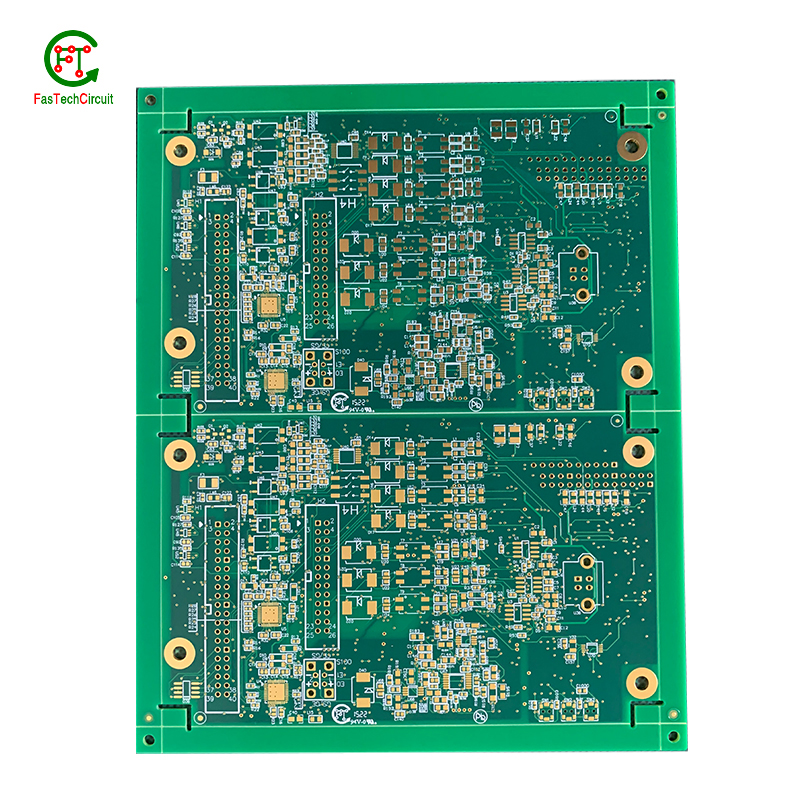
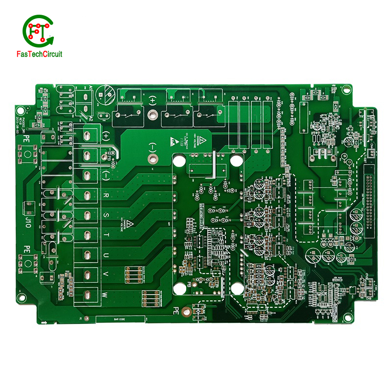
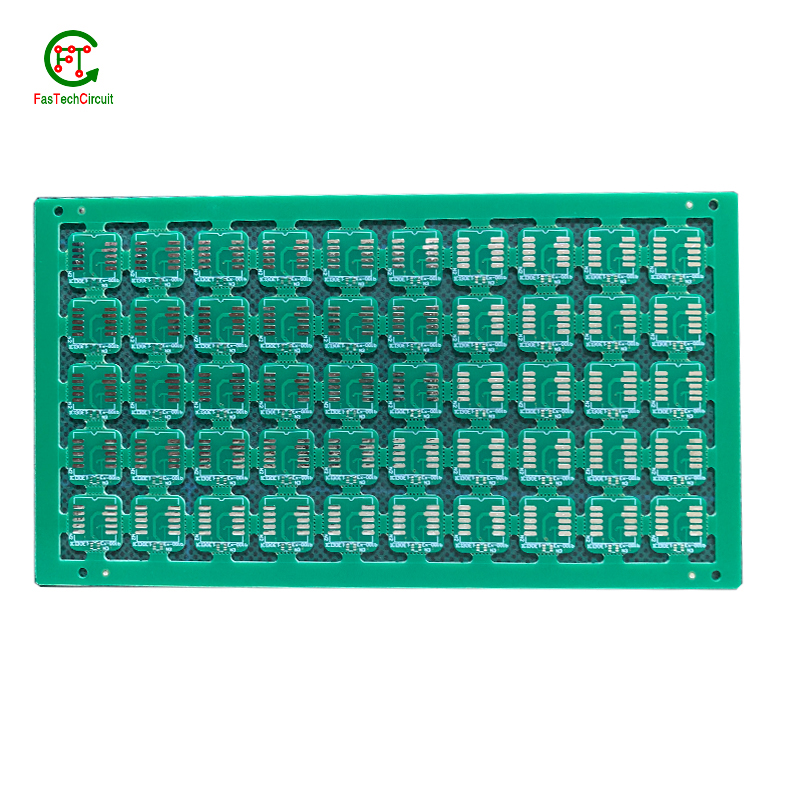
acd pcb design bearings FAQs Guide Welcome to our state-of-the-art PCB (Printed Circuit Board) products. We are proud to offer a comprehensive range of high-quality and versatile PCB solutions to meet the constantly evolving needs of the modern electronics industry.Our PCBs are expertly designed and manufactured using the latest technology and advanced techniques, ensuring reliability, durability, and exceptional performance for a wide range of applications. We understand the importance of precision and attention to detail in the production of PCBs and we are committed to meeting stringent quality standards.
2.What is the power rating for a acd pcb design?
3.What is the difference between a diode and a capacitor?
4.How are components attached to a acd pcb design?
5.How are high-speed/high-frequency acd pcb design tested and validated?
6.How are acd pcb design used in medical devices?
7.How are power and ground planes connected on a acd pcb design?
8.What is the difference between single-sided, double-sided, and multi-layer acd pcb design?
9.What does acd pcb design stand for?
10.How are acd pcb designs protected from moisture and humidity?
11.What techniques are used for reducing electromagnetic interference (EMI) on a acd pcb design?
12.What type of material is used for the silkscreen on a acd pcb design?
13.Can a acd pcb design be used for both power and signal transmission?
14.What is the future outlook for acd pcb design technology?
15.What types of acd pcb designs are there?
16.Can a acd pcb design be used with both through-hole and surface mount components?
17.How does a acd pcb design work?
1.What is the standard thickness for copper used in acd pcb designs?
The standard thickness for copper used in PCBs is 1 ounce (oz) or 35 micrometers (µm). However, thicker copper layers such as 2 oz or 3 oz can also be used for higher current carrying capacity or better heat dissipation. The thickness of copper used in a PCB is determined by the design requirements and the intended use of the board.
2.What is the power rating for a acd pcb design?
We maintain a certain amount of R&D investment every year and continuously improve operational efficiency to provide better services to our cooperative customers.
The power rating for a PCB (printed circuit board) can vary greatly depending on its size, design, and intended use. Generally, the power rating for a PCB is determined by the maximum amount of current it can safely handle without overheating or causing damage. This can range from a few milliamps for small, low-power circuits to several amps for larger, high-power circuits. It is important to consult the manufacturer's specifications or consult with an engineer to determine the specific power rating for a particular PCB.
3.What is the difference between a diode and a capacitor?
We have a first -class management team, and we pay attention to teamwork to achieve common goals.
A diode is an electronic component that allows current to flow in only one direction. It has two terminals, an anode and a cathode, and works by allowing current to flow from the anode to the cathode, but not in the reverse direction.
A capacitor, on the other hand, is an electronic component that stores electrical energy in an electric field. It has two conductive plates separated by an insulating material, and when a voltage is applied, one plate accumulates a positive charge and the other accumulates a negative charge. This allows the capacitor to store energy and release it when needed.
4.How are components attached to a acd pcb design?
We adhere to the principle of integrity and transparency, and establish long -term relationships with partners, and we attach great importance to this detail.
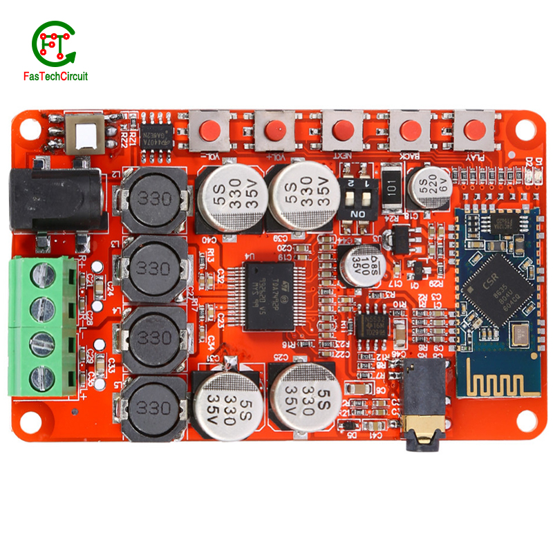
eads or pins of the component and melting solder onto them, whicComponents are attached to a PCB (printed circuit board) through a process called soldering. This involves heating the metal lh then solidifies and creates a strong electrical and mechanical connection between the component and the PCB. There are two main methods of soldering components onto a PCB:
1. Through-hole soldering: This method involves inserting the leads or pins of the component through pre-drilled holes on the PCB and soldering them on the opposite side of the board. This method is commonly used for larger components such as resistors, capacitors, and integrated circuits.
2. Surface mount soldering: This method involves soldering the component directly onto the surface of the PCB, without the need for pre-drilled holes. This is done using specialized equipment such as a soldering iron or a reflow oven. Surface mount components are smaller in size and are commonly used for more complex and compact electronic devices.
5.How are high-speed/high-frequency acd pcb design tested and validated?
Testing and validation are essential steps in the production process of high-speed and high-frequency printed circuit boards (PCBs). These specialized types of PCBs are used in a wide range of industries, including telecommunications, aerospace, and automotive, and require precision and reliability in their performance.
The testing and validation process for high-speed/high-frequency PCBs involves several steps to ensure that the final product meets the required specifications. This starts with design simulation and analysis using specialized software to verify the layout and electrical characteristics of the PCB.
Once the design is confirmed, prototype PCBs are manufactured and subjected to various tests, including signal integrity and power integrity tests. These tests evaluate the electrical performance of the PCB, such as its ability to transmit signals at high speeds and maintain signal integrity.
In addition to electrical tests, environmental and mechanical tests are also performed to assess the durability and reliability of the PCB under different conditions, such as temperature changes and mechanical stress.
The final step in the testing and validation process is the inspection and analysis of the tested PCBs. This involves a detailed review of the test results and any necessary modifications to meet the required specifications.
6.How are acd pcb design used in medical devices?
Printed Circuit Boards (PCBs) are essential components used in a wide range of medical devices, playing a crucial role in both diagnostic and treatment equipment. These devices require reliable and precise circuitry to accurately collect and process data, deliver therapies, and regulate medical procedures. PCBs are used in equipment such as MRI machines, pacemakers, defibrillators, and monitors, where their small size and high density make them ideal for compact and portable designs. In addition, PCBs are also used in medical implants, enabling a safe and secure connection between the device and the body. With their advanced technology, PCBs continue to be an integral part of the medical industry, ensuring the effectiveness and success of various medical procedures and treatments.
7.How are power and ground planes connected on a acd pcb design?
Power and ground planes are typically connected on a PCB through vias, which are small holes drilled through the layers of the PCB. These vias are filled with conductive material, such as copper, and allow for the flow of current between the power and ground planes. The vias are strategically placed throughout the PCB to ensure a low impedance connection between the power and ground planes. Additionally, traces or copper pours can also be used to connect the power and ground planes on different layers of the PCB.
8.What is the difference between single-sided, double-sided, and multi-layer acd pcb design?
We have established a good reputation and reliable partnerships within the acd pcb design industry.
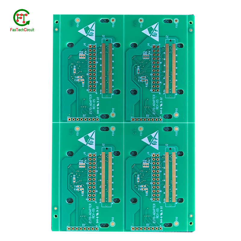
Single-sided PCB (Printed Circuit Board) is a type of PCB that has components and traces on only one side of the board. The other side is usually used for soldering and mounting the board onto a larger circuit.
Double-sided PCB is a type of PCB that has components and traces on both sides of the board. The traces on both sides are connected through vias, which are small holes drilled through the board and plated with metal to create an electrical connection.
Multi-layer PCB is a type of PCB that has multiple layers of conductive material and insulating material sandwiched together. The layers are connected through vias, allowing for more complex and compact circuit designs. Multi-layer PCBs are used in more advanced and high-performance electronic devices.
9.What does acd pcb design stand for?
We attach importance to the innovation ability and team spirit of employees, have advanced R & D facilities and laboratories, and have a good quality management system.
PCB stands for Printed Circuit Board.
10.How are acd pcb designs protected from moisture and humidity?
PCB (Printed Circuit Boards) are susceptible to damage from moisture and humidity, which can result in malfunction or even complete failure of electronic devices. Therefore, it is necessary to take measures to protect PCBs from these elements.
One way to protect PCBs from moisture is by using a conformal coating. This is a thin layer of protective material that is applied to the surface of the PCB. It acts as a barrier, preventing moisture from coming into contact with the sensitive components on the board.
Another method is to use moisture-resistant materials for the PCB itself. This can include using moisture-resistant coatings or laminates for the board, as well as corrosion-resistant materials for the conductors and connectors.
In addition to these preventive measures, PCBs can also be stored in controlled environments with low humidity levels. This can help to minimize the amount of moisture that comes into contact with the boards, reducing the risk of damage.
Regular maintenance and periodic testing can also help to ensure the continued protection of PCBs from moisture and humidity. By taking these precautions, electronic devices can maintain their functionality and reliability, even in environments with high humidity levels.
11.What techniques are used for reducing electromagnetic interference (EMI) on a acd pcb design?
Electromagnetic interference (EMI) is a disturbance caused by electromagnetic radiation that can disrupt the proper functioning of electronic devices. To reduce EMI on a PCB, a number of techniques can be employed. One common technique is to use a ground plane, which acts as a shield to block electromagnetic waves from interfering with the circuit. Another approach is to use proper placement and routing of components and traces to minimize the length of signal paths and reduce the chances of signal crossover. Additionally, using components like capacitors and ferrite beads can help to filter out high-frequency noise. Careful consideration and design of the PCB layout is also crucial in reducing EMI, as the placement, size, and orientation of components can impact electromagnetic emissions. By employing these techniques, EMI on a PCB can be effectively reduced, leading to improved performance and reliability of electronic devices.
12.What type of material is used for the silkscreen on a acd pcb design?
We have a wide range of acd pcb design customer groups and establishes long -term cooperative relationships with partners. The countries we provide services include .
The material used for the silkscreen on a PCB is typically a white or black ink made of epoxy or acrylic. It is applied using a screen printing process and is cured at high temperatures to ensure durability and resistance to chemicals and solvents.
13.Can a acd pcb design be used for both power and signal transmission?
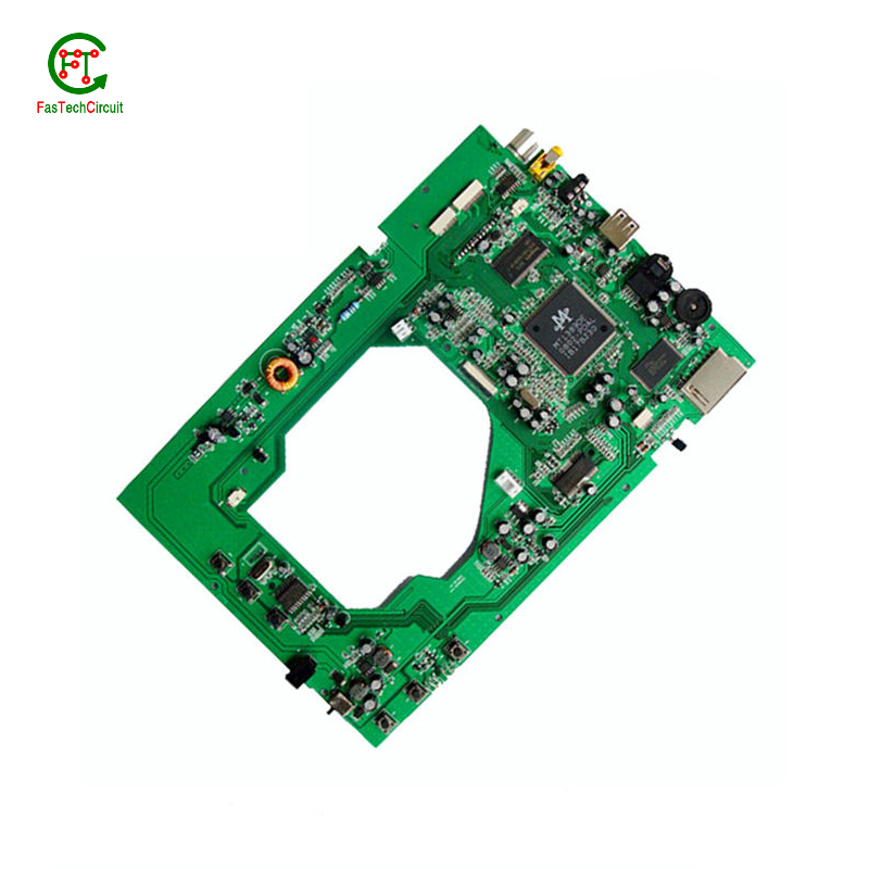
Yes, a PCB (printed circuit board) can be used for both power and signal transmission. This is commonly seen in electronic devices such as computers, smartphones, and other electronic devices. The PCB acts as a platform for connecting various components and circuits, including power sources and signal pathways. The power and signal traces on the PCB are designed to handle different levels of current and voltage to ensure efficient transmission and prevent interference between the two. However, it is important to properly design and layout the PCB to ensure proper separation and isolation of power and signal traces to avoid any potential issues.
14.What is the future outlook for acd pcb design technology?
Printed Circuit Boards, or PCBs, have been a vital component in electronic devices for decades. They serve as the foundation for the electrical connections and components that make our devices function properly. As technology continues to advance, so does the demand for smaller, faster, and more efficient PCBs. With the rise of IoT and smart devices, the future outlook for PCB technology is promising. It is expected that PCBs will become even more compact and complex, utilizing advanced materials and techniques such as 3D printing and flexible substrates. This will not only improve the performance of electronic devices, but also make them more durable and cost-effective. Furthermore, as sustainability becomes a growing concern, eco-friendly PCB materials and manufacturing processes are being developed to reduce environmental impact. With these advancements, it is safe to say that the future of PCB technology is bright and full of endless possibilities.
15.What types of acd pcb designs are there?
As one of the acd pcb design market leaders, we are known for innovation and reliability.
There are several types of PCBs, including single-sided, double-sided, multi-layer, and flexible PCBs. Single-sided PCBs have components mounted on one side and conductive traces on the other. Double-sided PCBs have components mounted on both sides with conductive traces connecting them. Multi-layer PCBs have several layers of conductive traces and insulating material sandwiched together. Flexible PCBs are made from a flexible plastic material, allowing them to bend and twist for use in applications where traditional rigid PCBs are not suitable. Each type of PCB serves a different purpose and can be used in a variety of electronic devices and applications.
16.Can a acd pcb design be used with both through-hole and surface mount components?
We continue to improve acd pcb design products and processes to improve efficiency.
Yes, a PCB (printed circuit board) can be designed to accommodate both through-hole and surface mount components. This is known as a mixed-technology PCB. The PCB will have both through-hole and surface mount pads and traces, allowing for the placement and soldering of both types of components. This type of PCB is commonly used in electronic devices that require a combination of through-hole and surface mount components for functionality.
17.How does a acd pcb design work?
We maintain a stable growth through reasonable capital operations, focus on industry development trends and cutting -edge technologies, and focus on product quality and safety performance.
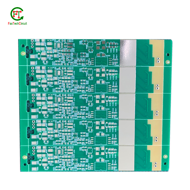
A PCB (Printed Circuit Board) is a thin board made of non-conductive material, such as fiberglass or plastic, with conductive pathways etched or printed onto its surface. These pathways, also known as traces, are used to connect electronic components on the board, such as resistors, capacitors, and integrated circuits.
The PCB works by providing a platform for the components to be mounted and connected in a specific circuit configuration. The traces on the board act as wires, allowing electricity to flow between the components and creating a complete circuit.
The process of creating a PCB involves several steps, including designing the circuit layout, printing or etching the traces onto the board, and attaching the components using soldering techniques. Once the components are attached, the board is tested to ensure that all connections are correct and functioning properly.
When a PCB is connected to a power source, electricity flows through the traces, powering the components and allowing them to perform their intended functions. The traces also act as a pathway for signals to travel between components, allowing for communication and data transfer within the circuit.
PCBs are used in a wide range of electronic devices, from simple household appliances to complex computer systems. They provide a compact and efficient way to connect and control electronic components, making them an essential part of modern technology.
RELATED PRODUCTS & SERVICE
pcb board manufacturing How To Contact US
PCB from 1 to 30 layers, HDI, Heavy Copper, Rigid-flex board with "pcb board manufacturing One-Stop" service.

