90 layout pcb
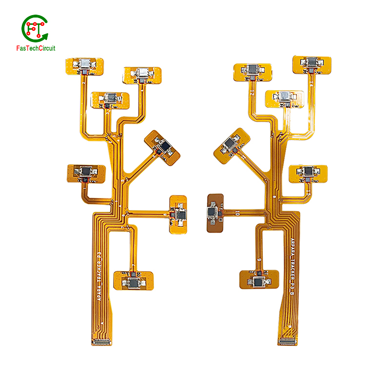
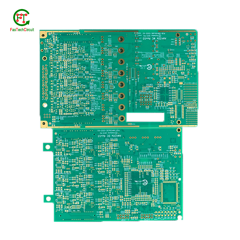
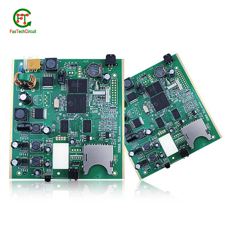
As a professional PCB manufacturer, our product range includes single-sided boards, double-sided boards, multi-layer boards, rigid-flexible connection boards, high-frequency boards, blind through boards, buried via boards, etc. At the same time, we also provide a variety of surface treatment processes, such as HASL, ENIG, OSP, metal spraying, etc., to meet the different needs of customers. We can provide one-stop OEM service with price advantage and fast delivery!
Our products are widely used in consumer electronics, communication equipment, industrial control, automotive electronics and other fields, and enjoy a high reputation in domestic and foreign markets. Our team has rich PCB manufacturing experience and professional skills and can provide customers with customized products and solutions. At the same time, we are also committed to continuously launching competitive and innovative products to meet the changing needs of customers. All our products comply with international quality standards and our customers come from different markets around the world. For example $keyworRd{4} etc.
| Model Number | customized PCBA |
| Type | pcba |
| Place of Origin | Guangdong, China |
| Brand Name | none |
| Copper Thickness | 1 oz |
| Supplier Type | OEM |
| Application | Electronics Device |
| Service | One-step Service |
| Layer | 1-37layers |
| Solder mask color | Blue.green.red.black.white.etc |
| Testing Service | 100% |
| Component size | 0201-1138mm |
| Component max height | 22mm |
| Min lead pitch | 0.3mm |
| Min BGA ball pitch | 0.4mm |
| Max PCB size | 598x487mm |
| Packaging Details | Vacuum package for bare PCB and ESD package for PCBA Printed Circuit Board Factory FPC Board PCBA Companies PCBA Assembly |
| Supply Ability | 49697 Piece/Pieces per Week |
| Quantity (pieces) | > 842 |
| Lead time (days) | 8 |
90 layout pcb bearings FAQs Guide Welcome to our state-of-the-art PCB (Printed Circuit Board) products. We are proud to offer a comprehensive range of high-quality and versatile PCB solutions to meet the constantly evolving needs of the modern electronics industry.Our PCBs are expertly designed and manufactured using the latest technology and advanced techniques, ensuring reliability, durability, and exceptional performance for a wide range of applications. We understand the importance of precision and attention to detail in the production of PCBs and we are committed to meeting stringent quality standards.
2.What is the minimum thickness of a 90 layout pcb?
3.How are components selected for a 90 layout pcb design?
4.How are 90 layout pcbs manufactured?
5.How are through-hole components soldered onto a 90 layout pcb?
6.How are 90 layout pcbs protected from moisture and humidity?
7.What is the minimum trace width and spacing on a 90 layout pcb?
8.Can a 90 layout pcb be repaired if damaged?
9.What is a 90 layout pcb?
10.What does 90 layout pcb stand for?
11.What are some common 90 layout pcb layout guidelines?
12.What type of solder is used for 90 layout pcb assembly?
13.Can 90 layout pcbs be used in high voltage applications?
14.What are the main components of a 90 layout pcb?
15.What are the advantages of using a 90 layout pcb?
16.What software is used for 90 layout pcb design?
17.What is the standard thickness for copper used in 90 layout pcbs?
18.What is the typical lifespan of a 90 layout pcb?
1.What is the future outlook for 90 layout pcb technology?
Printed Circuit Boards, or PCBs, have been a vital component in electronic devices for decades. They serve as the foundation for the electrical connections and components that make our devices function properly. As technology continues to advance, so does the demand for smaller, faster, and more efficient PCBs. With the rise of IoT and smart devices, the future outlook for PCB technology is promising. It is expected that PCBs will become even more compact and complex, utilizing advanced materials and techniques such as 3D printing and flexible substrates. This will not only improve the performance of electronic devices, but also make them more durable and cost-effective. Furthermore, as sustainability becomes a growing concern, eco-friendly PCB materials and manufacturing processes are being developed to reduce environmental impact. With these advancements, it is safe to say that the future of PCB technology is bright and full of endless possibilities.
2.What is the minimum thickness of a 90 layout pcb?
We are committed to providing personalized solutions and established long -term strategic cooperative relationships with customers.
The minimum thickness of a PCB (printed circuit board) can vary depending on the materials and manufacturing processes used. However, the standard minimum thickness for a single-sided PCB is 0.6mm (0.024 inches) and for a double-sided PCB it is 0.8mm (0.032 inches). Thinner PCBs can be made, but they may be more fragile and have limitations on the components and circuitry that can be used.
3.How are components selected for a 90 layout pcb design?
We pay attention to employee development and benefits, and provide a good working environment in order to improve the efficiency of employees and improve the quality management of 90 layout pcb products.
A power rating for a PCB, or Printed Circuit Board, is a measure of the maximum amount of power the board is able to safely handle. This rating takes into account the overall design and materials used in the creation of the PCB, as well as the environment in which it will be used. It is an important consideration in electronics and circuit design as exceeding the power rating can lead to overheating and potential damage to the board and connected components. Properly understanding and adhering to the power rating of a PCB is crucial for ensuring safe and efficient operation of electronic devices.
4.How are 90 layout pcbs manufactured?
We have the leading technology and innovation capabilities, and attach importance to employee training and development, and provide promotion opportunities.
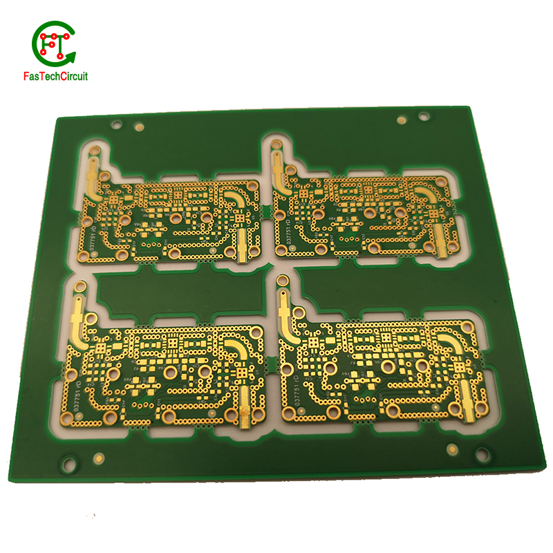
PCB are manufactured through a series of steps starting with designing the circuit layout. Once the design is finalized, the layout is printed on a special type of paper known as the “artwork”. This artwork is then transferred onto a copper-coated laminate board through a process called etching. The excess copper is removed, leaving behind the desired circuit pattern. The board is then drilled to create holes for components to be inserted. The next step involves adding a thin layer of solder mask to protect the circuit and adding a thin layer of copper to create traces. Finally, the components are added using a specialized machine, and the board goes through a series of tests to ensure proper functionality. Once the tests are passed, the board is cut and separated into individual PCBs for use in various electronic devices.
5.How are through-hole components soldered onto a 90 layout pcb?
Through-hole components are soldered onto a printed circuit board (PCB) using a process called wave soldering. First, the PCB is fitted with all the necessary through-hole components, such as resistors, capacitors, and diodes. Then, the board is passed over a wave of molten solder, which flows through the holes in the PCB and creates a secure connection between the component and the board. The excess solder is removed and the board is inspected to ensure all components are properly soldered. This method of soldering provides a strong and reliable connection for through-hole components, making it a popular choice for electronic assembly.
6.How are 90 layout pcbs protected from moisture and humidity?
PCB (Printed Circuit Boards) are susceptible to damage from moisture and humidity, which can result in malfunction or even complete failure of electronic devices. Therefore, it is necessary to take measures to protect PCBs from these elements.
One way to protect PCBs from moisture is by using a conformal coating. This is a thin layer of protective material that is applied to the surface of the PCB. It acts as a barrier, preventing moisture from coming into contact with the sensitive components on the board.
Another method is to use moisture-resistant materials for the PCB itself. This can include using moisture-resistant coatings or laminates for the board, as well as corrosion-resistant materials for the conductors and connectors.
In addition to these preventive measures, PCBs can also be stored in controlled environments with low humidity levels. This can help to minimize the amount of moisture that comes into contact with the boards, reducing the risk of damage.
Regular maintenance and periodic testing can also help to ensure the continued protection of PCBs from moisture and humidity. By taking these precautions, electronic devices can maintain their functionality and reliability, even in environments with high humidity levels.
7.What is the minimum trace width and spacing on a 90 layout pcb?
We operate our 90 layout pcb business with integrity and honesty.
The minimum trace width and spacing on a PCB can vary depending on the manufacturing process and the specific requirements of the design. However, a common industry standard for minimum trace width and spacing is 0.006 inches (0.1524 mm). This is typically used for standard PCBs with a 1 oz copper weight. For more complex designs or higher copper weights, the minimum trace width and spacing may need to be increased to ensure proper functionality and reliability. It is important to consult with the PCB manufacturer and follow their guidelines for minimum trace width and spacing to ensure a successful design.
8.Can a 90 layout pcb be repaired if damaged?
We focus on teamwork and communication to achieve common goals, We attach great importance to this detail.
Yes, a PCB (printed circuit board) can be repaired if it is damaged. The extent of the damage and the complexity of the circuit will determine the difficulty and feasibility of the repair. Some common methods for repairing a damaged PCB include:
1. Soldering: If the damage is limited to a few components or traces, they can be replaced or repaired by soldering new components or wires onto the board.
2. Trace repair: If a trace (conductive pathway) on the PCB is damaged or broken, it can be repaired by using a conductive ink or wire to bridge the gap.
3. Component replacement: If a specific component on the PCB is damaged, it can be replaced with a new one. This requires identifying the damaged component and sourcing a replacement.
4. PCB rework: In some cases, the entire PCB may need to be reworked, which involves removing and replacing multiple components and traces.
9.What is a 90 layout pcb?
We pay attention to user experience and product quality, and provide the best product quality and lowest production cost for cooperative customers.
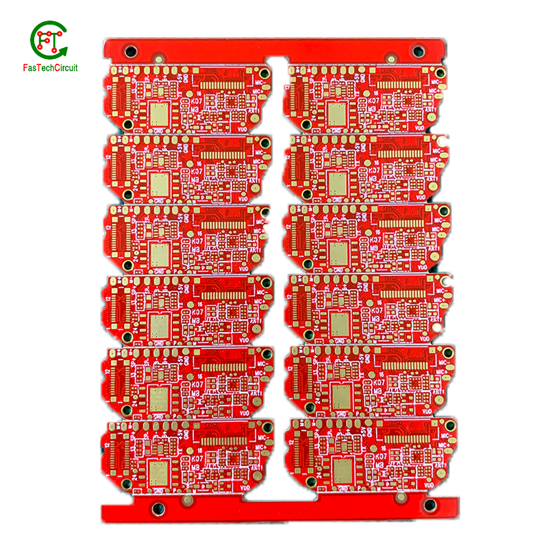
A PCB (Printed Circuit Board) is a flat board made of non-conductive material, such as fiberglass, with conductive pathways etched or printed onto it. It is used to mechanically support and electrically connect electronic components using conductive tracks, pads, and other features etched from copper sheets laminated onto a non-conductive substrate. PCBs are commonly used in electronic devices such as computers, smartphones, and televisions to provide a platform for the components to be mounted and connected together. They are also used in a variety of other applications, including automotive, aerospace, and medical devices.
10.What does 90 layout pcb stand for?
We attach importance to the innovation ability and team spirit of employees, have advanced R & D facilities and laboratories, and have a good quality management system.
PCB stands for Printed Circuit Board.
11.What are some common 90 layout pcb layout guidelines?
We should have a stable supply chain and logistics capabilities, and provide customers with high -quality, low -priced 90 layout pcb products.
Thermal considerations play a crucial role in the design of printed circuit boards (PCBs). The concept of heat management is critical as excessive heat can lead to reduced performance and potential damage to the electronic components on the board. This is why thermal considerations are carefully taken into account during PCB design. Designers must carefully consider factors such as the size, placement, and orientation of components on the board to ensure efficient heat dissipation. They also need to factor in the type and thickness of the board material, as well as incorporate proper ventilation and heat sinks to prevent overheating. By carefully considering these thermal aspects during the design process, the resulting PCBs can perform optimally and have a longer lifespan.
12.What type of solder is used for 90 layout pcb assembly?
The most commonly used solder for PCB assembly is a lead-free solder, specifically a tin-silver-copper (SnAgCu) alloy. This type of solder is preferred due to its high melting point, good wetting properties, and compatibility with surface mount technology (SMT) components. Other types of solder that may be used include tin-lead (SnPb) solder and lead-free alternatives such as tin-copper (SnCu) and tin-bismuth (SnBi) alloys. The specific type of solder used may vary depending on the application and industry standards.
13.Can 90 layout pcbs be used in high voltage applications?
We have advantages in marketing and channel expansion. Suppliers have established good cooperative relations, continuously improved workflows, improved efficiency and productivity, and provided customers with high -quality products and services.
Yes, PCBs (printed circuit boards) can be used in high voltage applications. However, the design and construction of the PCB must be carefully considered to ensure it can withstand the high voltage without causing damage or malfunction. This may include using specialized materials, increasing the spacing between components, and implementing proper insulation and grounding techniques. It is important to consult with a qualified engineer or designer when using PCBs in high voltage applications to ensure safety and reliability.
14.What are the main components of a 90 layout pcb?
We continuously upgrade our skills and knowledge to adapt to changing 90 layout pcb market needs.
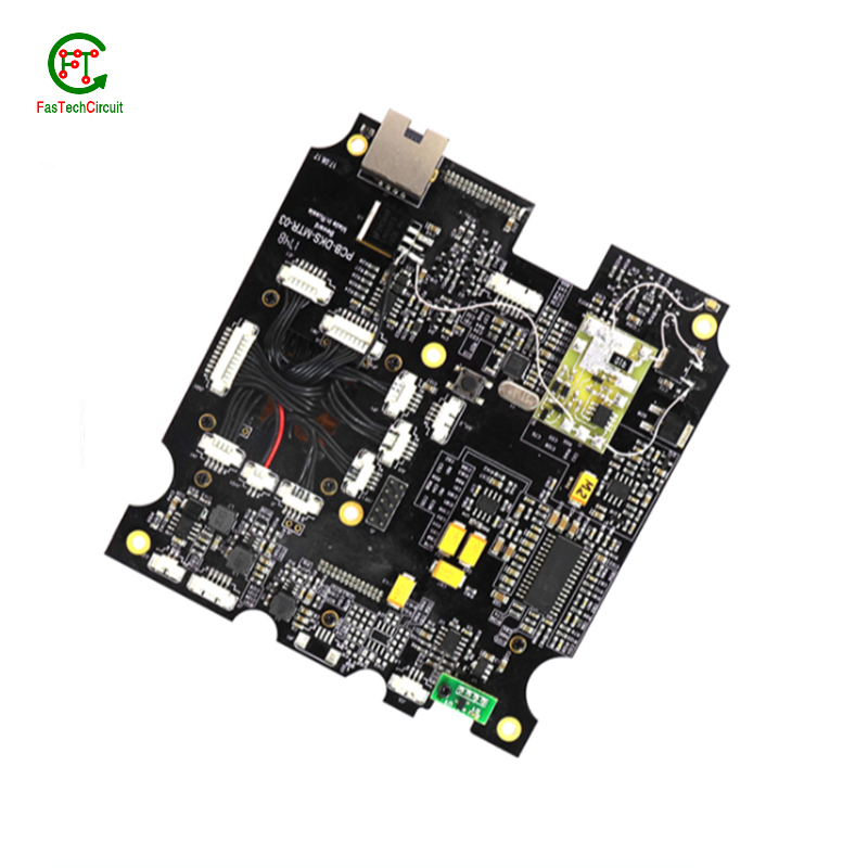
A typical PCB consists of several vital components, including a substrate material, copper traces, solder mask, silk screen, and plated through-holes. The substrate material acts as the base and provides mechanical support for the board. Copper traces, usually made of thin lines of copper foil, serve as the conductive paths for transmitting electrical signals. The solder mask, applied as a protective layer, prevents accidental short circuits and corrosion. Silk screen, a layer of ink-based labeling, aids in component identification. Lastly, plated through-holes enable electrical connection between different layers of the PCB board. These components work together to form a fully functioning PCB.
15.What are the advantages of using a 90 layout pcb?
We are centered on customers and always pay attention to customers' needs for 90 layout pcb products.
There are several advantages of using a PCB (Printed Circuit Board). Firstly, a PCB provides a compact and organized layout for electronic components, which makes it easier for technicians to troubleshoot and repair any issues. Secondly, it reduces the chances of loose connections and short circuits, which can be a major safety concern. Thirdly, PCBs are cost-effective and can be easily mass-produced, making them a popular choice for large-scale production. Additionally, they offer durability and stability, ensuring long-lasting performance. Finally, PCBs also allow for easy integration of new components, making it easier to upgrade or modify the electronic devices.
16.What software is used for 90 layout pcb design?
Our 90 layout pcb products have competitive and differentiated advantages, and actively promote digital transformation and innovation.
Some popular software used for PCB design include:
1. Altium Designer
2. Eagle PCB
3. KiCad
4. OrCAD
5. PADS
6. Proteus
7. DipTrace
8. EasyEDA
9. CircuitMaker
10. DesignSpark PCB

17.What is the standard thickness for copper used in 90 layout pcbs?
The standard thickness for copper used in PCBs is 1 ounce (oz) or 35 micrometers (µm). However, thicker copper layers such as 2 oz or 3 oz can also be used for higher current carrying capacity or better heat dissipation. The thickness of copper used in a PCB is determined by the design requirements and the intended use of the board.
18.What is the typical lifespan of a 90 layout pcb?
90 layout pcb is not a product only, but also can help you comes to money-making.
The typical lifespan of a PCB (printed circuit board) can vary greatly depending on various factors such as the quality of materials used, environmental conditions, and usage. In general, a well-designed and properly manufactured PCB can last for 10-20 years or more. However, some PCBs may fail prematurely due to factors such as corrosion, thermal stress, or mechanical damage. Regular maintenance and proper handling can also extend the lifespan of a PCB.
RELATED PRODUCTS & SERVICE
pcb board manufacturing How To Contact US
PCB from 1 to 30 layers, HDI, Heavy Copper, Rigid-flex board with "pcb board manufacturing One-Stop" service.

