3d pcb design free
With excellent project management skills, open communication, constant follow-up, and customer-centric values, we will make electronic development run smoothly. High-quality production is even harder to find. All our products comply with international quality standards and our customers come from different markets around the world. For example Suriname,Benin,Japan,Madagascar etc.
| Model Number | customized PCBA |
| Type | pcba |
| Place of Origin | Guangdong, China |
| Brand Name | none |
| Copper Thickness | 1 oz |
| Supplier Type | OEM |
| Application | Electronics Device |
| Service | One-step Service |
| Layer | 1-33layers |
| Solder mask color | Blue.green.red.black.white.etc |
| Testing Service | 100% |
| Component size | 0201-1131mm |
| Component max height | 34mm |
| Min lead pitch | 0.4mm |
| Min BGA ball pitch | 0.3mm |
| Max PCB size | 550x472mm |
| Packaging Details | Vacuum package for bare PCB and ESD package for PCBA Printed Circuit Board Factory FPC Board PCBA Companies PCBA Assembly |
| Supply Ability | 51729 Piece/Pieces per Week |
| Quantity (pieces) | > 862 |
| Lead time (days) | 15 |
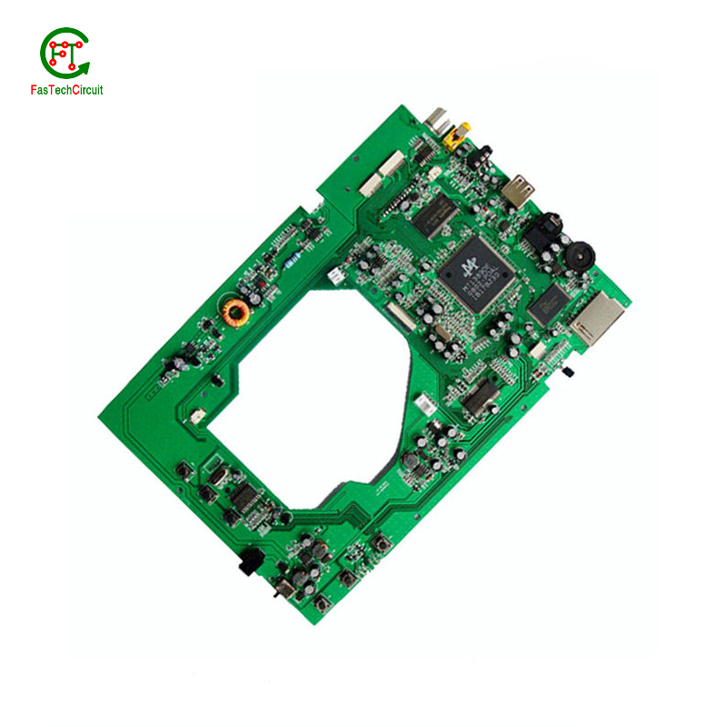
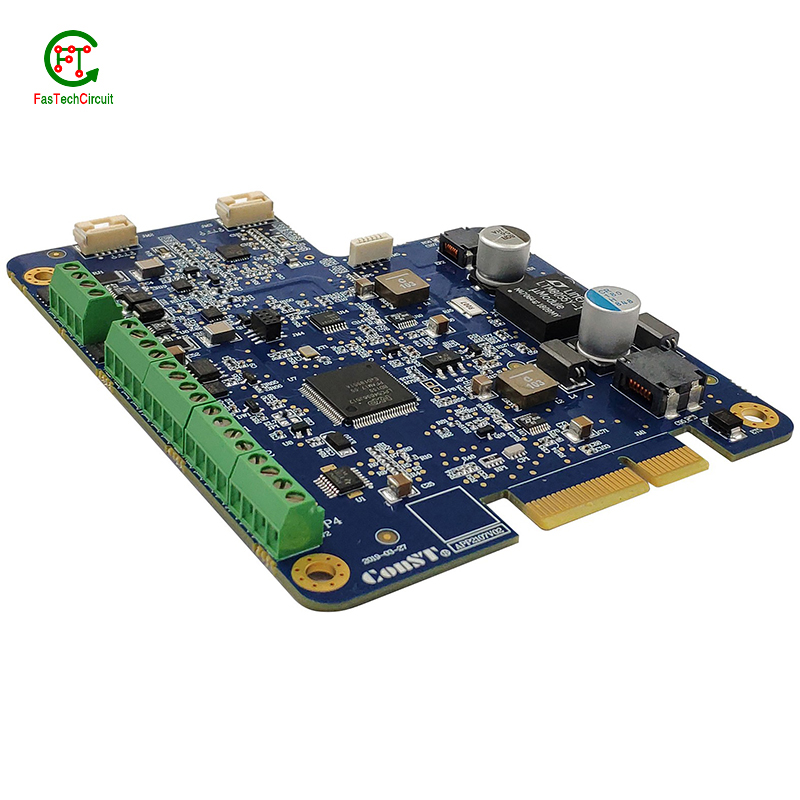
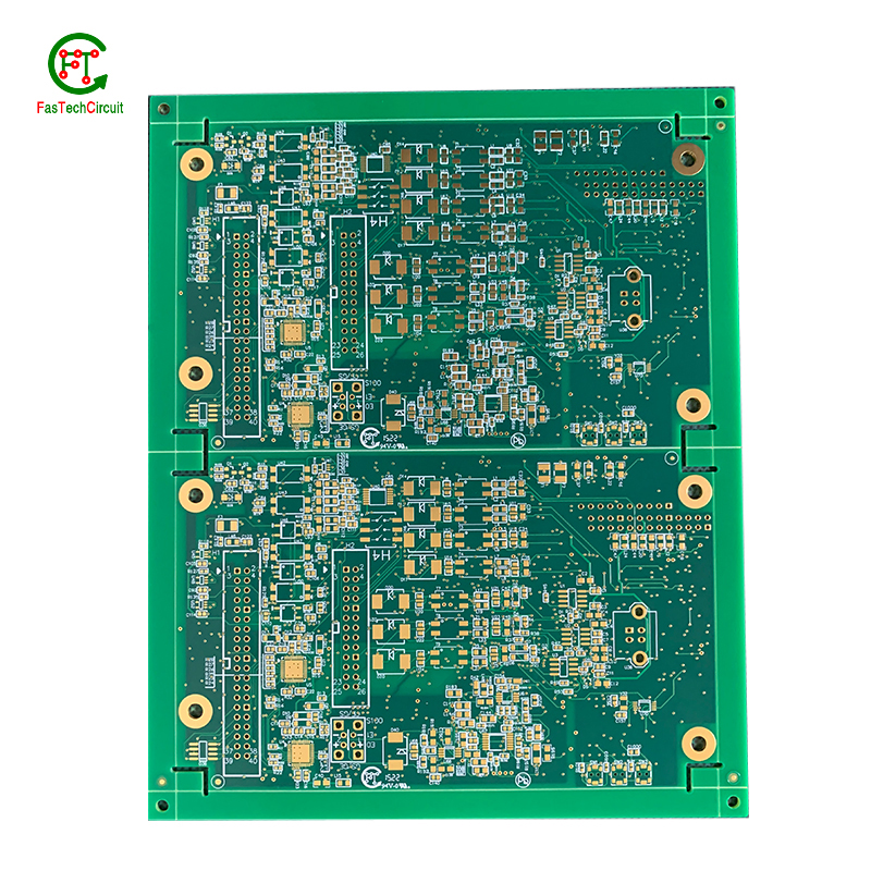
3d pcb design free bearings FAQs Guide Welcome to our state-of-the-art PCB (Printed Circuit Board) products. We are proud to offer a comprehensive range of high-quality and versatile PCB solutions to meet the constantly evolving needs of the modern electronics industry.Our PCBs are expertly designed and manufactured using the latest technology and advanced techniques, ensuring reliability, durability, and exceptional performance for a wide range of applications. We understand the importance of precision and attention to detail in the production of PCBs and we are committed to meeting stringent quality standards.
2.What is the role of vias on a 3d pcb design free?
3.How are components selected for a 3d pcb design free design?
4.What is the power rating for a 3d pcb design free?
5.What are the benefits of using surface mount technology (SMT) for 3d pcb design free?
6.What does 3d pcb design free stand for?
7.What type of material is used for the silkscreen on a 3d pcb design free?
8.What is the role of a data sheet in 3d pcb design free design?
9.What is the role of automated optical inspection (AOI) in 3d pcb design free production?
10.What is the standard thickness for copper used in 3d pcb design frees?
11.How are components attached to a 3d pcb design free?
12.Can a 3d pcb design free be repaired if damaged?
13.What is the maximum size of a 3d pcb design free?
14.What is the function of a resistor on a 3d pcb design free?
15.What is the future outlook for 3d pcb design free technology?
1.How are signal integrity issues addressed in 3d pcb design free design?
We focus on our customers' needs and strive to meet their expectations, so we take this very seriously.
Signal integrity issues are a common concern in PCB design, as they can greatly affect the performance and reliability of electronic systems. These issues arise from high-speed signal transmissions on the board, which can result in degraded signals, data errors, and even system failures. In order to address these issues, PCB designers must consider various factors such as layout, routing, and component placement to ensure proper signal integrity. This involves implementing signal protection measures such as controlled impedance routing, signal shielding, and minimizing signal crosstalk. Additionally, designers may use simulation and analysis tools to identify and resolve any potential signal integrity problems before the PCB goes into production. By carefully addressing signal integrity issues in the design phase, PCBs can achieve optimal performance and functionality.
2.What is the role of vias on a 3d pcb design free?
Our company has many years of 3d pcb design free experience and expertise.
Vias play a crucial role in connecting different layers of a printed circuit board (PCB). These small, plated holes act as conductive paths, allowing signals and power to pass through the board and reach various components. Vias are also essential for routing traces from one layer to another, optimizing the layout and reducing the size and complexity of the board. Additionally, vias provide structural support and improve thermal management by facilitating heat dissipation.
3.How are components selected for a 3d pcb design free design?
We pay attention to employee development and benefits, and provide a good working environment in order to improve the efficiency of employees and improve the quality management of 3d pcb design free products.
A power rating for a PCB, or Printed Circuit Board, is a measure of the maximum amount of power the board is able to safely handle. This rating takes into account the overall design and materials used in the creation of the PCB, as well as the environment in which it will be used. It is an important consideration in electronics and circuit design as exceeding the power rating can lead to overheating and potential damage to the board and connected components. Properly understanding and adhering to the power rating of a PCB is crucial for ensuring safe and efficient operation of electronic devices.
4.What is the power rating for a 3d pcb design free?
We maintain a certain amount of R&D investment every year and continuously improve operational efficiency to provide better services to our cooperative customers.
The power rating for a PCB (printed circuit board) can vary greatly depending on its size, design, and intended use. Generally, the power rating for a PCB is determined by the maximum amount of current it can safely handle without overheating or causing damage. This can range from a few milliamps for small, low-power circuits to several amps for larger, high-power circuits. It is important to consult the manufacturer's specifications or consult with an engineer to determine the specific power rating for a particular PCB.
5.What are the benefits of using surface mount technology (SMT) for 3d pcb design free?
We focus on innovation and continuous improvement to maintain a competitive advantage.
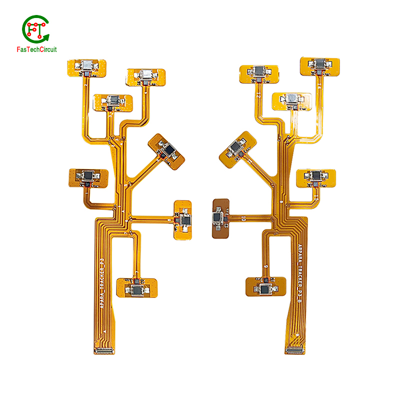
Surface mount technology (SMT) is a popular method for assembling printed circuit boards (PCBs) that offers numerous benefits over traditional through-hole components. Firstly, SMT components are smaller and more compact, allowing for greater PCB density and reducing the overall size of the board. This makes SMT ideal for increasingly miniaturized electronics, such as smartphones and wearables. Additionally, SMT components are typically cheaper and easier to manufacture, leading to cost savings in both materials and labor. SMT also allows for automated assembly, resulting in faster and more efficient production processes. Furthermore, the smaller size of SMT components leads to improved electrical performance due to decreased parasitic effects and shorter signal paths. This makes SMT ideal for high-frequency applications.
6.What does 3d pcb design free stand for?
We attach importance to the innovation ability and team spirit of employees, have advanced R & D facilities and laboratories, and have a good quality management system.
PCB stands for Printed Circuit Board.
7.What type of material is used for the silkscreen on a 3d pcb design free?
We have a wide range of 3d pcb design free customer groups and establishes long -term cooperative relationships with partners. The countries we provide services include .
The material used for the silkscreen on a PCB is typically a white or black ink made of epoxy or acrylic. It is applied using a screen printing process and is cured at high temperatures to ensure durability and resistance to chemicals and solvents.
8.What is the role of a data sheet in 3d pcb design free design?
A data sheet is an essential tool for PCB design, providing vital information and specifications for all of the components used in the design process. It contains detailed technical data, such as dimensions, electrical ratings, and performance characteristics, that allow designers to make informed decisions when selecting and placing components on a PCB. By referencing the data sheet, designers can ensure that each component is properly integrated into the overall design, following any necessary guidelines or restrictions. Additionally, data sheets also provide necessary information for the layout and routing of traces on the PCB, ensuring that the design can meet required performance specifications.
9.What is the role of automated optical inspection (AOI) in 3d pcb design free production?
Automated optical inspection (AOI) plays a crucial role in the production of printed circuit boards (PCBs). It is a technology that uses advanced imaging techniques to detect and identify defects or errors on a PCB, such as missing components, incorrect placement, and faulty soldering. AOI has become an essential step in the production process as it helps manufacturers ensure the quality and reliability of their PCBs. By detecting and identifying defects at an early stage, AOI can significantly reduce the number of defects and increase the efficiency of the production process. Furthermore, AOI is able to perform inspections at a much faster rate and with higher accuracy compared to manual inspection, making it an indispensable tool for PCB production.
10.What is the standard thickness for copper used in 3d pcb design frees?
The standard thickness for copper used in PCBs is 1 ounce (oz) or 35 micrometers (µm). However, thicker copper layers such as 2 oz or 3 oz can also be used for higher current carrying capacity or better heat dissipation. The thickness of copper used in a PCB is determined by the design requirements and the intended use of the board.
11.How are components attached to a 3d pcb design free?
We adhere to the principle of integrity and transparency, and establish long -term relationships with partners, and we attach great importance to this detail.
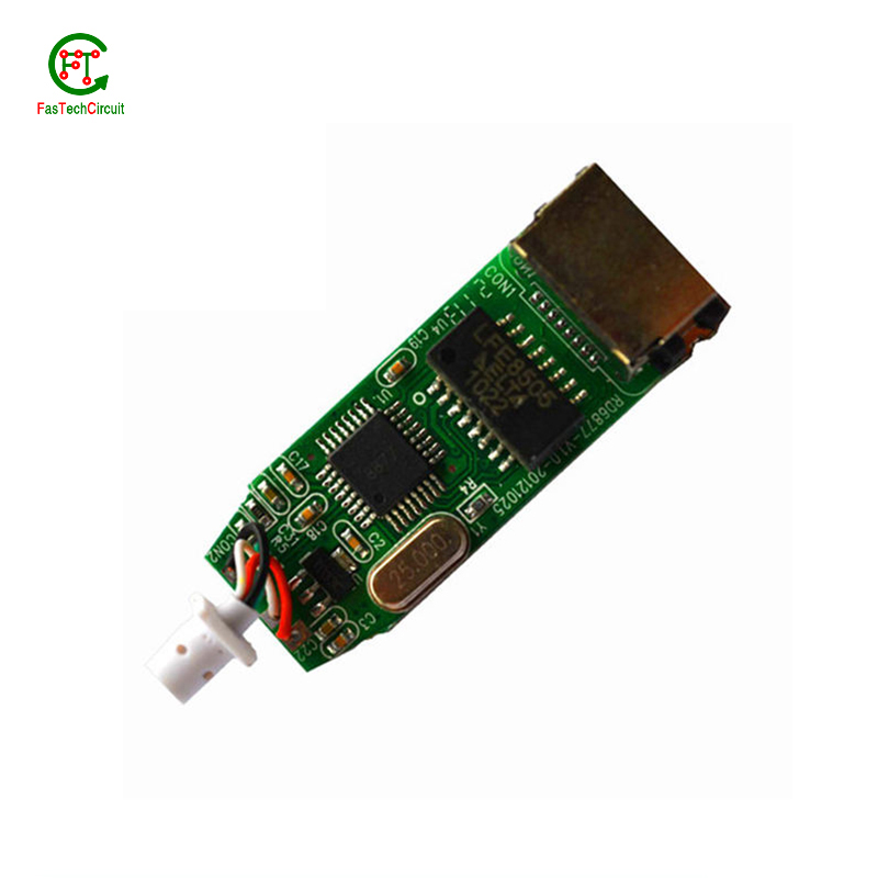
eads or pins of the component and melting solder onto them, whicComponents are attached to a PCB (printed circuit board) through a process called soldering. This involves heating the metal lh then solidifies and creates a strong electrical and mechanical connection between the component and the PCB. There are two main methods of soldering components onto a PCB:
1. Through-hole soldering: This method involves inserting the leads or pins of the component through pre-drilled holes on the PCB and soldering them on the opposite side of the board. This method is commonly used for larger components such as resistors, capacitors, and integrated circuits.
2. Surface mount soldering: This method involves soldering the component directly onto the surface of the PCB, without the need for pre-drilled holes. This is done using specialized equipment such as a soldering iron or a reflow oven. Surface mount components are smaller in size and are commonly used for more complex and compact electronic devices.
12.Can a 3d pcb design free be repaired if damaged?
We focus on teamwork and communication to achieve common goals, We attach great importance to this detail.
Yes, a PCB (printed circuit board) can be repaired if it is damaged. The extent of the damage and the complexity of the circuit will determine the difficulty and feasibility of the repair. Some common methods for repairing a damaged PCB include:
1. Soldering: If the damage is limited to a few components or traces, they can be replaced or repaired by soldering new components or wires onto the board.
2. Trace repair: If a trace (conductive pathway) on the PCB is damaged or broken, it can be repaired by using a conductive ink or wire to bridge the gap.
3. Component replacement: If a specific component on the PCB is damaged, it can be replaced with a new one. This requires identifying the damaged component and sourcing a replacement.
4. PCB rework: In some cases, the entire PCB may need to be reworked, which involves removing and replacing multiple components and traces.
13.What is the maximum size of a 3d pcb design free?
We pay attention to the introduction and training of talents, scientifically regulate the management system, and focus on cultural construction and team cohesion.
The maximum size of a PCB (printed circuit board) can vary depending on the manufacturer and theircapabilities. However, the industry standard maximum size for a single PCB panel is typically around 18 inches by 24 inches (457 mm by 610 mm). Larger PCBs can be created by combining multiple panels together. Some manufacturers may also have the capability to create custom-sized PCBs that exceed the industry standard maximum size.
14.What is the function of a resistor on a 3d pcb design free?
We are a new 3d pcb design free manufacturer.
The ground plane on a printed circuit board (PCB) serves as a reference point for the electrical signals that flow throughout the circuit. It is typically a large area of copper that is connected to the negative terminal of the power supply and serves as a low-impedance return path for current. Its main purpose is to provide a stable and uniform ground connection for the components on the PCB, helping to reduce electromagnetic interference and ensuring proper signal grounding. Without a ground plane, the circuit may experience noise and other unwanted effects, potentially causing malfunctions or disruptions in its functionality. Therefore, the ground plane plays a crucial role in ensuring the overall performance and reliability of a PCB.
15.What is the future outlook for 3d pcb design free technology?
Printed Circuit Boards, or PCBs, have been a vital component in electronic devices for decades. They serve as the foundation for the electrical connections and components that make our devices function properly. As technology continues to advance, so does the demand for smaller, faster, and more efficient PCBs. With the rise of IoT and smart devices, the future outlook for PCB technology is promising. It is expected that PCBs will become even more compact and complex, utilizing advanced materials and techniques such as 3D printing and flexible substrates. This will not only improve the performance of electronic devices, but also make them more durable and cost-effective. Furthermore, as sustainability becomes a growing concern, eco-friendly PCB materials and manufacturing processes are being developed to reduce environmental impact. With these advancements, it is safe to say that the future of PCB technology is bright and full of endless possibilities.
RELATED PRODUCTS & SERVICE
pcb board manufacturing How To Contact US
PCB from 1 to 30 layers, HDI, Heavy Copper, Rigid-flex board with "pcb board manufacturing One-Stop" service.

