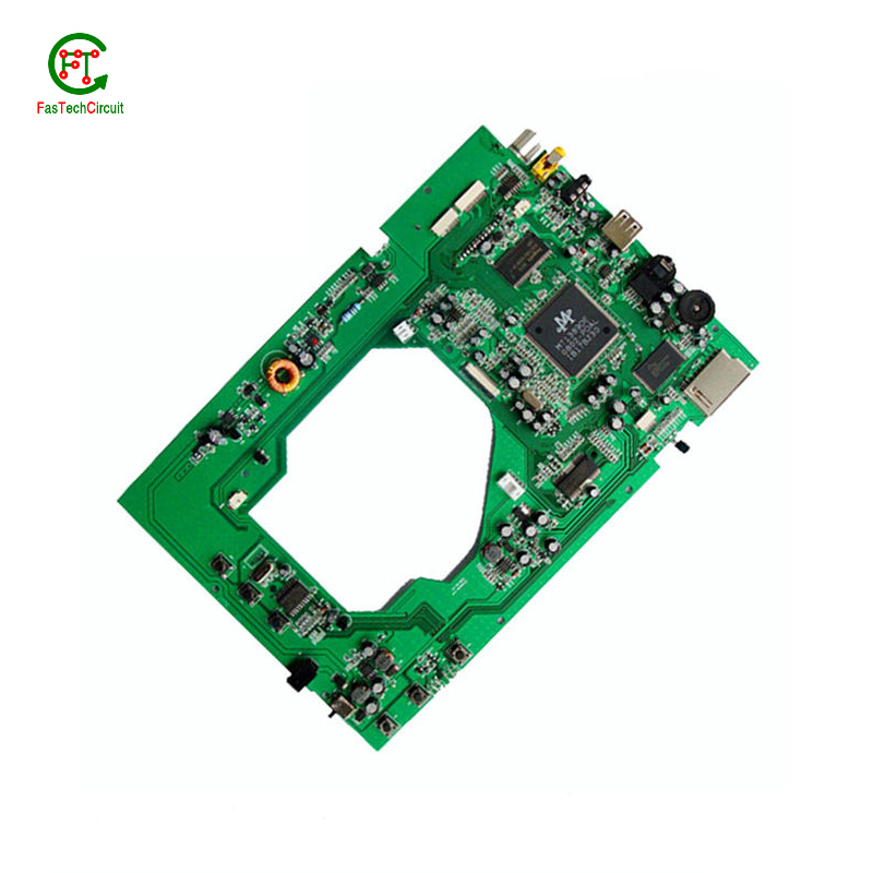
211-150588 pcb board
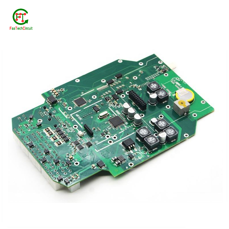
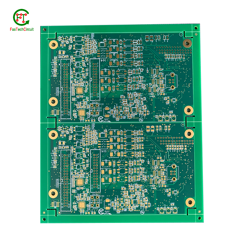
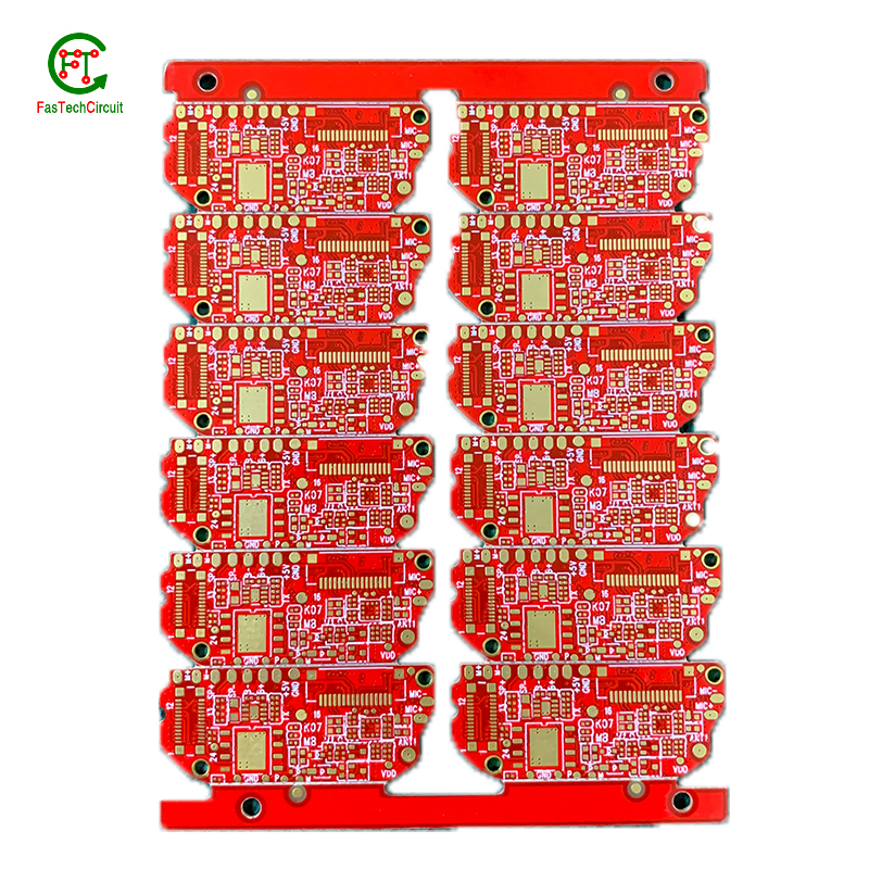
FasTechCircuit's products cover single-panel, double-panel, multi-layer boards, rigid boards, flexible boards, hybrid (rigid-soft) boards and other types. According to customer needs and application fields, we can provide PCB products of different materials and processes, such as FR-4, aluminum substrates, ceramic substrates, etc. At the same time, we can also provide a variety of surface treatment processes according to customer needs, such as OSP, HASL, ENIG, etc., to ensure the reliability and stability of the circuit board. We also provide non-standard customization services and can customize production according to the special requirements provided by customers to meet their personalized needs.
FasTechCircuit's printed circuit board products are widely used in communication equipment, industrial control, consumer electronics, computers and peripheral equipment, medical equipment, aerospace and other fields. Our products undergo strict quality control, have high precision, high reliability and stability, and can meet customers' high requirements for electronic products. Our products are very popular in India,Maldives,Turkey,Malaysia,Nigeria,Slovakia, the United States and Japan. Won high praise from customers.
| Number of Layers | 4 layer |
| Base Material | gold sinking |
| Board Thickness | 3.1MM |
| Board Size | 315M*645MM |
| Model Number | 4 layer pcb |
| Type | pcb |
| Place of Origin | Original |
| Brand Name | Original |
| Copper Thickness | 3OZ |
| Min. Hole Size | custom made |
| Min. Line Width | custom made |
| Min. Line Spacing | custom made |
| Surface Finishing | custom made |
| Impedance control | +/- 6% |
| Warpage | less than 1% |
| Packaging Details | New and Original, factory sealed packing, it will be pack in one of these packing type: Tube, Tray, Tape and Reel, Tape and Box, Bulk packing, Bag and etc. Please kindly contact us for more details. |
| Supply Ability | 5268 Piece/Pieces per Week |
| Quantity (pieces) | > 18835 |
| Lead time (days) | 12 |
211-150588 pcb board bearings FAQs Guide Welcome to our state-of-the-art PCB (Printed Circuit Board) products. We are proud to offer a comprehensive range of high-quality and versatile PCB solutions to meet the constantly evolving needs of the modern electronics industry.Our PCBs are expertly designed and manufactured using the latest technology and advanced techniques, ensuring reliability, durability, and exceptional performance for a wide range of applications. We understand the importance of precision and attention to detail in the production of PCBs and we are committed to meeting stringent quality standards.
2.Can 211-150588 pcb boards be used in automotive applications?
3.What software is used for 211-150588 pcb board design?
4.Can 211-150588 pcb boards be customized?
5.What is the role of a data sheet in 211-150588 pcb board design?
6.How are holes drilled into a 211-150588 pcb board?
7.What is the lifespan of a 211-150588 pcb board under harsh environmental conditions?
8.What is the difference between an analog and a digital signal on a 211-150588 pcb board?
9.What is the minimum size of a through-hole component that can be used on a 211-150588 pcb board?
10.What is the power rating for a 211-150588 pcb board?
11.What type of material is used for the silkscreen on a 211-150588 pcb board?
12.What is the minimum trace width and spacing on a 211-150588 pcb board?
13.What is the purpose of a ground plane on a 211-150588 pcb board?
14.What is the process of etching a 211-150588 pcb board?
1.What is the difference between a gold-plated and a tin-plated 211-150588 pcb board?
A gold-plated PCB (Printed Circuit Board) is a type of PCB that has a thin layer of gold coating on its surface. This layer is added through a process called electroplating and is commonly used to protect the PCB components from corrosion and increase the conductivity. On the other hand, a tin-plated PCB has a layer of tin coating on its surface, which is also applied through electroplating. Unlike gold plating, tin plating is mainly used to prevent oxidization and improve solderability.
2.Can 211-150588 pcb boards be used in automotive applications?
Yes, PCBs (printed circuit boards) can be used in automotive applications. They are commonly used in various electronic systems in vehicles, such as engine control units, infotainment systems, and safety systems. PCBs offer a compact and reliable way to connect and control electronic components in vehicles. They are also designed to withstand harsh environmental conditions, such as temperature fluctuations, vibrations, and moisture, making them suitable for use in automotive applications.
3.What software is used for 211-150588 pcb board design?
Our 211-150588 pcb board products have competitive and differentiated advantages, and actively promote digital transformation and innovation.
Some popular software used for PCB design include:
1. Altium Designer
2. Eagle PCB
3. KiCad
4. OrCAD
5. PADS
6. Proteus
7. DipTrace
8. EasyEDA
9. CircuitMaker
10. DesignSpark PCB
4.Can 211-150588 pcb boards be customized?
We should enjoy a good reputation in the industry, and we can increase the added value of the products of cooperative customers through technological innovation.
Yes, PCBs (printed circuit boards) can be customized to meet specific design requirements. This can include changes to the size, shape, number of layers, and placement of components on the board. Customization can also involve the use of specialized materials, finishes, and manufacturing processes to meet specific performance or environmental requirements. PCB manufacturers often offer design services to help customers create custom PCBs that meet their unique needs.
5.What is the role of a data sheet in 211-150588 pcb board design?
A data sheet is an essential tool for PCB design, providing vital information and specifications for all of the components used in the design process. It contains detailed technical data, such as dimensions, electrical ratings, and performance characteristics, that allow designers to make informed decisions when selecting and placing components on a PCB. By referencing the data sheet, designers can ensure that each component is properly integrated into the overall design, following any necessary guidelines or restrictions. Additionally, data sheets also provide necessary information for the layout and routing of traces on the PCB, ensuring that the design can meet required performance specifications.
6.How are holes drilled into a 211-150588 pcb board?
We actively participate in the 211-150588 pcb board industry associations and organization activities. The corporate social responsibility performed well, and the focus of brand building and promotion.
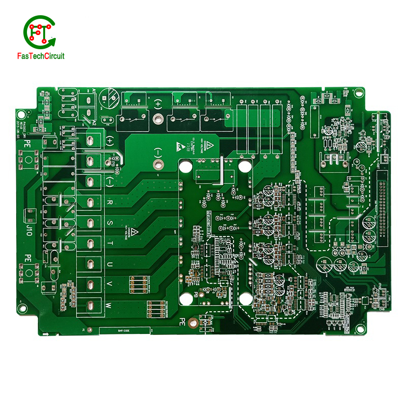
Drilling holes into printed circuit boards (PCBs) is a critical part of the PCB manufacturing process. These holes are used for mounting electronic components and for creating electrical connections between different layers of the board. There are two main methods for drilling holes into a PCB – mechanical drilling and laser drilling. Mechanical drilling involves using a high speed drill bit to physically drill through the board, while laser drilling uses a high-powered laser to vaporize the material and create the holes. Both methods have their own advantages and are often used in combination to achieve the desired hole sizes and precision. Regardless of the method, the holes are carefully planned and executed to ensure the successful production of a high-quality PCB.
7.What is the lifespan of a 211-150588 pcb board under harsh environmental conditions?
The lifespan of a PCB (printed circuit board) under harsh environmental conditions can vary greatly depending on the specific conditions and the quality of the PCB. In general, a well-designed and high-quality PCB can last for 10-20 years under harsh conditions such as extreme temperatures, humidity, and exposure to chemicals or vibrations. However, if the PCB is not properly designed or manufactured, its lifespan can be significantly shorter, potentially lasting only a few years or even months. Factors such as the type of materials used, the thickness of the copper traces, and the quality of the solder joints can also affect the lifespan of a PCB under harsh environmental conditions. Regular maintenance and proper handling can also help extend the lifespan of a PCB.
8.What is the difference between an analog and a digital signal on a 211-150588 pcb board?
An analog signal is a continuous signal that varies in amplitude and frequency over time. It can take on any value within a given range and is typically represented by a smooth, continuous waveform. Analog signals are used to transmit information such as audio, video, and sensor data.
A digital signal, on the other hand, is a discrete signal that can only take on a limited number of values. It is represented by a series of binary digits (0s and 1s) and can only have two states: on or off. Digital signals are used to transmit information in the form of data and are commonly used in digital electronics such as computers and smartphones.
On a PCB, the main difference between analog and digital signals lies in the way they are processed and transmitted. Analog signals require specialized components such as amplifiers and filters to maintain their integrity, while digital signals can be processed and transmitted using digital logic circuits. Additionally, analog signals are more susceptible to noise and interference, while digital signals are more immune to these factors.
9.What is the minimum size of a through-hole component that can be used on a 211-150588 pcb board?
We continue to invest in research and development and continue to launch innovative products.
The minimum size of a through-hole component that can be used on a PCB depends on the capabilities of the PCB manufacturer and the design requirements of the circuit. Generally, the minimum size for a through-hole component is around 0.2mm in diameter, but some manufacturers may be able to produce smaller sizes. It is important to consult with the manufacturer and consider the design requirements to determine the appropriate size for a through-hole component on a PCB.
10.What is the power rating for a 211-150588 pcb board?
We maintain a certain amount of R&D investment every year and continuously improve operational efficiency to provide better services to our cooperative customers.
The power rating for a PCB (printed circuit board) can vary greatly depending on its size, design, and intended use. Generally, the power rating for a PCB is determined by the maximum amount of current it can safely handle without overheating or causing damage. This can range from a few milliamps for small, low-power circuits to several amps for larger, high-power circuits. It is important to consult the manufacturer's specifications or consult with an engineer to determine the specific power rating for a particular PCB.
11.What type of material is used for the silkscreen on a 211-150588 pcb board?
We have a wide range of 211-150588 pcb board customer groups and establishes long -term cooperative relationships with partners. The countries we provide services include .
The material used for the silkscreen on a PCB is typically a white or black ink made of epoxy or acrylic. It is applied using a screen printing process and is cured at high temperatures to ensure durability and resistance to chemicals and solvents.
12.What is the minimum trace width and spacing on a 211-150588 pcb board?
We operate our 211-150588 pcb board business with integrity and honesty.
The minimum trace width and spacing on a PCB can vary depending on the manufacturing process and the specific requirements of the design. However, a common industry standard for minimum trace width and spacing is 0.006 inches (0.1524 mm). This is typically used for standard PCBs with a 1 oz copper weight. For more complex designs or higher copper weights, the minimum trace width and spacing may need to be increased to ensure proper functionality and reliability. It is important to consult with the PCB manufacturer and follow their guidelines for minimum trace width and spacing to ensure a successful design.
13.What is the purpose of a ground plane on a 211-150588 pcb board?
I have a comprehensive after -sales service system, which can pay attention to market trends in time and adjust our strategy in a timely manner.
A decoupling capacitor is an essential component on a PCB (Printed Circuit Board) which is used to reduce or eliminate high frequency noise between different components. It acts as a buffer between the power supply and other circuit components, by storing electrical charge and then releasing it when there is a sudden change in the supply voltage. This helps to stabilize the power supply, providing a steady and noise-free flow of electricity to the circuit. Furthermore, decoupling capacitors also help to filter out any unwanted signals that may cause interference or disruptions in the proper functioning of the circuit.
14.What is the process of etching a 211-150588 pcb board?
We have flexible production capacity. Whether you are large orders or small orders, you can produce and release goods in a timely manner to meet customer needs.
PCB (Printed Circuit Board) etching is the process of creating a circuit pattern on a copper-clad board by using chemical etchants to selectively remove the unwanted copper. The process begins by transferring the circuit design onto a copper-clad board using various methods such as printing or photolithography. Next, the board is coated with a resist material, which protects the areas of copper that will eventually become the circuit traces. The board is then placed in an etching solution, typically a mixture of acid and water, which dissolves the unprotected copper. Once the desired circuit pattern is etched into the board, the resist material is removed, and the board is cleaned and inspected for any imperfections. PCB etching is a crucial step in the manufacturing of PCBs, as it creates the necessary conductive pathways for electronic components to be mounted and interconnected, making it an essential process in the production of electronic devices.
RELATED PRODUCTS & SERVICE
pcb board manufacturing How To Contact US
PCB from 1 to 30 layers, HDI, Heavy Copper, Rigid-flex board with "pcb board manufacturing One-Stop" service.

