4440 ic pcb layout
| Base Material | FR-4/CEM-1/CEM-3/Polyimild/PTFE/Rogers |
| Board Thickness | 0.1-4mm |
| Model Number | Custom PCB & PCB Assembly |
| Type | Aluminum PCB |
| Brand Name | FC |
| Copper Thickness | 0.2-2mil(7-45um) |
| Min. Hole Size | 0.1mm(4mil)for HDI / 0.15mm(6mil) |
| Min. Line Width | 0.075mm/0.075mm(3mil/3mil) |
| Min. Line Spacing | 0.003'' |
| Surface Finishing | HASL/OSP/Ag/ENIG/ENEPIG/Immersion silver/Tin |
| Board Size | Custom |
| Model Number | Customized |
| Base Material | FR4 Aluminum CEM-1 94V0 |
| Surface Finishing | HASLENIG OSP |
| Number of layer | 1-14layer |
| Other service | Components purchasing and assem |
| ly Solder mask | White Black Green Blue,Red,etc. |
| Dsign service | Available |
| Testing | Function testing |
| Certificate | RoHS, ISO/TS16949, ISO9001 |
| Name | High Quality led light aluminum pcb printed circuit board |
| Packaging Details | Vaccum package and standard carton outside High Quality led light aluminum pcb printed circuit board |
| Supply Ability | 59391 Square Meter/Square Meters per Month |
| Quantity (pieces) | > 14042 |
| Lead time (days) | 11 |
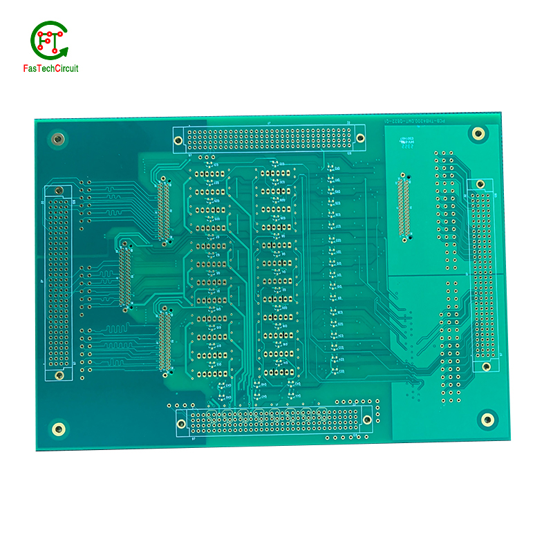
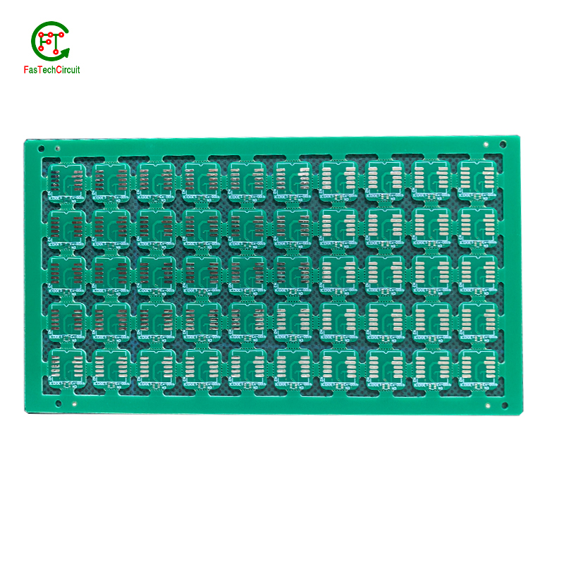
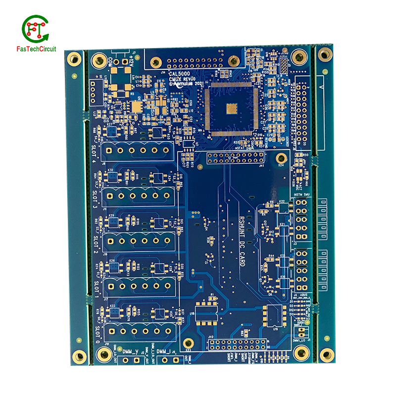
4440 ic pcb layout bearings FAQs Guide Welcome to our state-of-the-art PCB (Printed Circuit Board) products. We are proud to offer a comprehensive range of high-quality and versatile PCB solutions to meet the constantly evolving needs of the modern electronics industry.Our PCBs are expertly designed and manufactured using the latest technology and advanced techniques, ensuring reliability, durability, and exceptional performance for a wide range of applications. We understand the importance of precision and attention to detail in the production of PCBs and we are committed to meeting stringent quality standards.
2.Can 4440 ic pcb layouts be used for high-speed data transmission?
3.What is the future outlook for 4440 ic pcb layout technology?
4.What type of solder is used for 4440 ic pcb layout assembly?
5.What types of 4440 ic pcb layouts are there?
6.How are through-hole components soldered onto a 4440 ic pcb layout?
7.Can 4440 ic pcb layouts be used in automotive applications?
8.What is the difference between a gold-plated and a tin-plated 4440 ic pcb layout?
9.How are signal integrity issues addressed in 4440 ic pcb layout design?
10.How are 4440 ic pcb layouts tested for quality control?
11.What does 4440 ic pcb layout stand for?
12.How are high-speed/high-frequency 4440 ic pcb layout tested and validated?
13.How are components attached to a 4440 ic pcb layout?
1.How are signal traces routed on a 4440 ic pcb layout?
Signal traces are an essential element of a PCB, responsible for carrying electronic signals between components and ensuring proper communication and functionality of the circuit. To route these traces, designers use specialized software to determine the most efficient and optimal path for each signal, taking into account factors such as signal integrity, trace length, and potential interference. This process involves careful planning, as well as techniques such as vias, ground and power planes, and differential pairs to minimize noise and maintain signal integrity.
2.Can 4440 ic pcb layouts be used for high-speed data transmission?
Yes, PCBs (printed circuit boards) can be used for high-speed data transmission. PCBs are commonly used in electronic devices and systems to connect and route electrical signals between components. They are designed to have specific trace widths, lengths, and impedance to ensure efficient and reliable transmission of high-speed signals. Additionally, PCBs can be designed with specialized materials and techniques, such as controlled impedance and differential signaling, to further optimize their performance for high-speed data transmission.
3.What is the future outlook for 4440 ic pcb layout technology?
Printed Circuit Boards, or PCBs, have been a vital component in electronic devices for decades. They serve as the foundation for the electrical connections and components that make our devices function properly. As technology continues to advance, so does the demand for smaller, faster, and more efficient PCBs. With the rise of IoT and smart devices, the future outlook for PCB technology is promising. It is expected that PCBs will become even more compact and complex, utilizing advanced materials and techniques such as 3D printing and flexible substrates. This will not only improve the performance of electronic devices, but also make them more durable and cost-effective. Furthermore, as sustainability becomes a growing concern, eco-friendly PCB materials and manufacturing processes are being developed to reduce environmental impact. With these advancements, it is safe to say that the future of PCB technology is bright and full of endless possibilities.
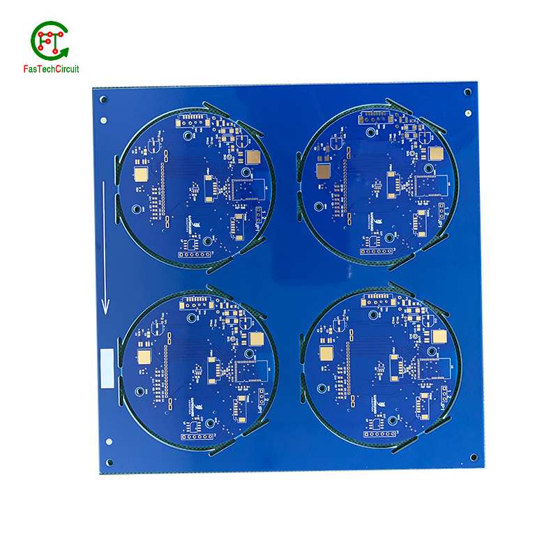
4.What type of solder is used for 4440 ic pcb layout assembly?
The most commonly used solder for PCB assembly is a lead-free solder, specifically a tin-silver-copper (SnAgCu) alloy. This type of solder is preferred due to its high melting point, good wetting properties, and compatibility with surface mount technology (SMT) components. Other types of solder that may be used include tin-lead (SnPb) solder and lead-free alternatives such as tin-copper (SnCu) and tin-bismuth (SnBi) alloys. The specific type of solder used may vary depending on the application and industry standards.
5.What types of 4440 ic pcb layouts are there?
As one of the 4440 ic pcb layout market leaders, we are known for innovation and reliability.
There are several types of PCBs, including single-sided, double-sided, multi-layer, and flexible PCBs. Single-sided PCBs have components mounted on one side and conductive traces on the other. Double-sided PCBs have components mounted on both sides with conductive traces connecting them. Multi-layer PCBs have several layers of conductive traces and insulating material sandwiched together. Flexible PCBs are made from a flexible plastic material, allowing them to bend and twist for use in applications where traditional rigid PCBs are not suitable. Each type of PCB serves a different purpose and can be used in a variety of electronic devices and applications.
6.How are through-hole components soldered onto a 4440 ic pcb layout?
Through-hole components are soldered onto a printed circuit board (PCB) using a process called wave soldering. First, the PCB is fitted with all the necessary through-hole components, such as resistors, capacitors, and diodes. Then, the board is passed over a wave of molten solder, which flows through the holes in the PCB and creates a secure connection between the component and the board. The excess solder is removed and the board is inspected to ensure all components are properly soldered. This method of soldering provides a strong and reliable connection for through-hole components, making it a popular choice for electronic assembly.
7.Can 4440 ic pcb layouts be used in automotive applications?
Yes, PCBs (printed circuit boards) can be used in automotive applications. They are commonly used in various electronic systems in vehicles, such as engine control units, infotainment systems, and safety systems. PCBs offer a compact and reliable way to connect and control electronic components in vehicles. They are also designed to withstand harsh environmental conditions, such as temperature fluctuations, vibrations, and moisture, making them suitable for use in automotive applications.
8.What is the difference between a gold-plated and a tin-plated 4440 ic pcb layout?
A gold-plated PCB (Printed Circuit Board) is a type of PCB that has a thin layer of gold coating on its surface. This layer is added through a process called electroplating and is commonly used to protect the PCB components from corrosion and increase the conductivity. On the other hand, a tin-plated PCB has a layer of tin coating on its surface, which is also applied through electroplating. Unlike gold plating, tin plating is mainly used to prevent oxidization and improve solderability.
9.How are signal integrity issues addressed in 4440 ic pcb layout design?
We focus on our customers' needs and strive to meet their expectations, so we take this very seriously.
Signal integrity issues are a common concern in PCB design, as they can greatly affect the performance and reliability of electronic systems. These issues arise from high-speed signal transmissions on the board, which can result in degraded signals, data errors, and even system failures. In order to address these issues, PCB designers must consider various factors such as layout, routing, and component placement to ensure proper signal integrity. This involves implementing signal protection measures such as controlled impedance routing, signal shielding, and minimizing signal crosstalk. Additionally, designers may use simulation and analysis tools to identify and resolve any potential signal integrity problems before the PCB goes into production. By carefully addressing signal integrity issues in the design phase, PCBs can achieve optimal performance and functionality.
10.How are 4440 ic pcb layouts tested for quality control?
We have broad development space in domestic and foreign markets. 4440 ic pcb layout have great advantages in terms of price, quality, and delivery date.
PCB (Printed Circuit Board) testing is a critical step in the quality control process of electronic products. It ensures that all components and connections on the board are functioning correctly and that the PCB meets the required standards and specifications.
The testing process typically starts with a visual inspection to identify any visible defects, such as incorrect soldering or damaged components. Next, electrical testing is conducted to check the functionality of each individual component and the overall circuit.
One common method of testing is the use of a test fixture, which applies signals to the PCB and checks for correct responses. Other methods include automated optical inspection (AOI) and in-circuit testing (ICT).
Once the initial testing is completed, the PCB may undergo environmental testing to simulate real-life conditions and ensure its reliability and durability. This includes temperature and humidity cycling, vibration and shock testing, and more.
11.What does 4440 ic pcb layout stand for?
We attach importance to the innovation ability and team spirit of employees, have advanced R & D facilities and laboratories, and have a good quality management system.
PCB stands for Printed Circuit Board.
12.How are high-speed/high-frequency 4440 ic pcb layout tested and validated?
Testing and validation are essential steps in the production process of high-speed and high-frequency printed circuit boards (PCBs). These specialized types of PCBs are used in a wide range of industries, including telecommunications, aerospace, and automotive, and require precision and reliability in their performance.
The testing and validation process for high-speed/high-frequency PCBs involves several steps to ensure that the final product meets the required specifications. This starts with design simulation and analysis using specialized software to verify the layout and electrical characteristics of the PCB.
Once the design is confirmed, prototype PCBs are manufactured and subjected to various tests, including signal integrity and power integrity tests. These tests evaluate the electrical performance of the PCB, such as its ability to transmit signals at high speeds and maintain signal integrity.
In addition to electrical tests, environmental and mechanical tests are also performed to assess the durability and reliability of the PCB under different conditions, such as temperature changes and mechanical stress.
The final step in the testing and validation process is the inspection and analysis of the tested PCBs. This involves a detailed review of the test results and any necessary modifications to meet the required specifications.
13.How are components attached to a 4440 ic pcb layout?
We adhere to the principle of integrity and transparency, and establish long -term relationships with partners, and we attach great importance to this detail.
eads or pins of the component and melting solder onto them, whicComponents are attached to a PCB (printed circuit board) through a process called soldering. This involves heating the metal lh then solidifies and creates a strong electrical and mechanical connection between the component and the PCB. There are two main methods of soldering components onto a PCB:
1. Through-hole soldering: This method involves inserting the leads or pins of the component through pre-drilled holes on the PCB and soldering them on the opposite side of the board. This method is commonly used for larger components such as resistors, capacitors, and integrated circuits.
2. Surface mount soldering: This method involves soldering the component directly onto the surface of the PCB, without the need for pre-drilled holes. This is done using specialized equipment such as a soldering iron or a reflow oven. Surface mount components are smaller in size and are commonly used for more complex and compact electronic devices.
RELATED PRODUCTS & SERVICE
pcb board manufacturing How To Contact US
PCB from 1 to 30 layers, HDI, Heavy Copper, Rigid-flex board with "pcb board manufacturing One-Stop" service.

