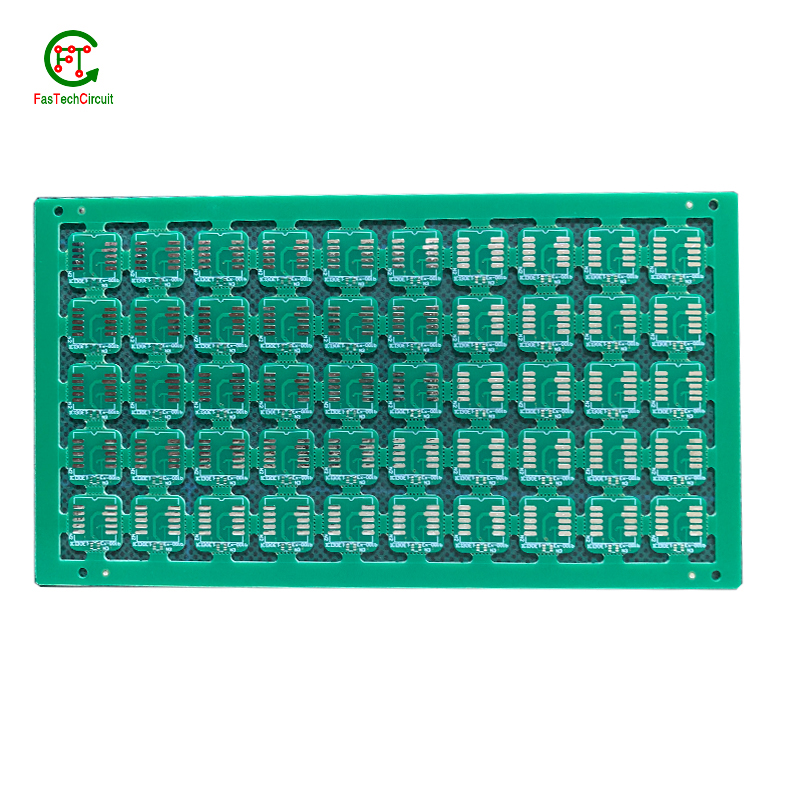
8x8 led matrix pcb layout
Our customers mainly come from 50 regions around the world including Mauritania,Liberia,Dominica,Brazil,Belgium,Jan Mayen. As an ISO9001 certified electronics assembly manufacturer, all projects we undertake are fully compliant with ROHS standards and quality assurance. Based on our engineering excellence and production capabilities in technology areas such as material analysis and storage, advanced equipment, reliability testing (AOI, X-RAY, ICT testing and functional testing), efficient SMT and THT assembly, we are recognized as a global leader in A PCBA supplier that more and more customers have trusted for a long time. Welcome to visit us for inspection at any time.
| Number of Layers | 4 layer |
| Base Material | gold sinking |
| Board Thickness | 1.7MM |
| Board Size | 290M*583MM |
| Model Number | 4 layer pcb |
| Type | pcb |
| Place of Origin | Original |
| Brand Name | Original |
| Copper Thickness | 3OZ |
| Min. Hole Size | custom made |
| Min. Line Width | custom made |
| Min. Line Spacing | custom made |
| Surface Finishing | custom made |
| Impedance control | +/- 4% |
| Warpage | less than 1% |
| Packaging Details | New and Original, factory sealed packing, it will be pack in one of these packing type: Tube, Tray, Tape and Reel, Tape and Box, Bulk packing, Bag and etc. Please kindly contact us for more details. |
| Supply Ability | 5538 Piece/Pieces per Week |
| Quantity (pieces) | > 14681 |
| Lead time (days) | 13 |
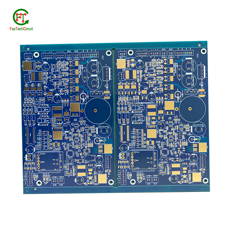
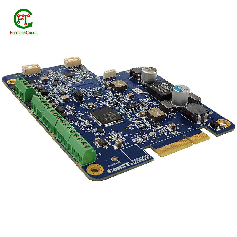
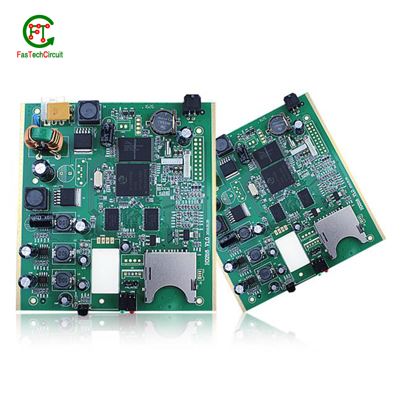
8x8 led matrix pcb layout bearings FAQs Guide Welcome to our state-of-the-art PCB (Printed Circuit Board) products. We are proud to offer a comprehensive range of high-quality and versatile PCB solutions to meet the constantly evolving needs of the modern electronics industry.Our PCBs are expertly designed and manufactured using the latest technology and advanced techniques, ensuring reliability, durability, and exceptional performance for a wide range of applications. We understand the importance of precision and attention to detail in the production of PCBs and we are committed to meeting stringent quality standards.
2.What is the future outlook for 8x8 led matrix pcb layout technology?
3.What are the advantages of using a 8x8 led matrix pcb layout?
4.How are thermal considerations taken into account during 8x8 led matrix pcb layout design?
5.What is noise coupling and how can it be prevented on a 8x8 led matrix pcb layout?
6.What is the minimum trace width and spacing on a 8x8 led matrix pcb layout?
7.Can 8x8 led matrix pcb layouts be used in high voltage applications?
8.Can 8x8 led matrix pcb layouts be used for high-temperature applications?
9.How are components selected for a 8x8 led matrix pcb layout design?
10.What is the minimum thickness of a 8x8 led matrix pcb layout?
11.What is the role of automated optical inspection (AOI) in 8x8 led matrix pcb layout production?
12.What is the power rating for a 8x8 led matrix pcb layout?
13.What are the benefits of using surface mount technology (SMT) for 8x8 led matrix pcb layout?
14.How are signal traces routed on a 8x8 led matrix pcb layout?
15.What does 8x8 led matrix pcb layout stand for?
1.What is the difference between a gold-plated and a tin-plated 8x8 led matrix pcb layout?
A gold-plated PCB (Printed Circuit Board) is a type of PCB that has a thin layer of gold coating on its surface. This layer is added through a process called electroplating and is commonly used to protect the PCB components from corrosion and increase the conductivity. On the other hand, a tin-plated PCB has a layer of tin coating on its surface, which is also applied through electroplating. Unlike gold plating, tin plating is mainly used to prevent oxidization and improve solderability.
2.What is the future outlook for 8x8 led matrix pcb layout technology?
Printed Circuit Boards, or PCBs, have been a vital component in electronic devices for decades. They serve as the foundation for the electrical connections and components that make our devices function properly. As technology continues to advance, so does the demand for smaller, faster, and more efficient PCBs. With the rise of IoT and smart devices, the future outlook for PCB technology is promising. It is expected that PCBs will become even more compact and complex, utilizing advanced materials and techniques such as 3D printing and flexible substrates. This will not only improve the performance of electronic devices, but also make them more durable and cost-effective. Furthermore, as sustainability becomes a growing concern, eco-friendly PCB materials and manufacturing processes are being developed to reduce environmental impact. With these advancements, it is safe to say that the future of PCB technology is bright and full of endless possibilities.
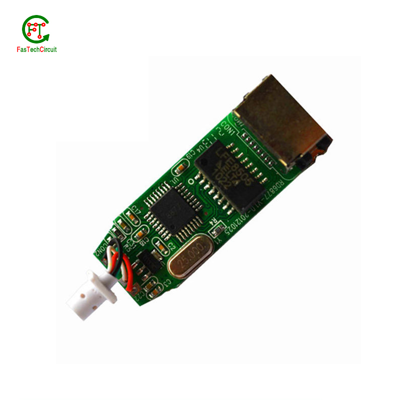
3.What are the advantages of using a 8x8 led matrix pcb layout?
We are centered on customers and always pay attention to customers' needs for 8x8 led matrix pcb layout products.
There are several advantages of using a PCB (Printed Circuit Board). Firstly, a PCB provides a compact and organized layout for electronic components, which makes it easier for technicians to troubleshoot and repair any issues. Secondly, it reduces the chances of loose connections and short circuits, which can be a major safety concern. Thirdly, PCBs are cost-effective and can be easily mass-produced, making them a popular choice for large-scale production. Additionally, they offer durability and stability, ensuring long-lasting performance. Finally, PCBs also allow for easy integration of new components, making it easier to upgrade or modify the electronic devices.
4.How are thermal considerations taken into account during 8x8 led matrix pcb layout design?
As one of the top 8x8 led matrix pcb layout manufacturers in China, we take this very seriously.
Thermal considerations are crucial in the design of printed circuit boards (PCB), as excessive heat can greatly affect the performance and lifespan of electronic components. PCB design engineers must carefully consider thermal management strategies, such as proper placement of heat-generating components, effective heat dissipation techniques, and optimal selection of materials. Thermal simulations and analysis are also commonly used to evaluate and optimize the PCB design to ensure that the temperature of the PCB and its components are within safe limits. By taking into account these thermal considerations, the finished PCB can perform reliably and efficiently, ensuring the overall quality and function of electronic devices.
5.What is noise coupling and how can it be prevented on a 8x8 led matrix pcb layout?
We are a professional 8x8 led matrix pcb layout company dedicated to providing high quality products and services.
Signal traces on a PCB (printed circuit board) are routes created to connect electronic components and allow for the transfer of electrical signals. These traces are typically made from copper and are carefully routed and designed to ensure efficient and reliable signal flow. The routing of signal traces is a critical aspect of PCB design and involves determining the best paths for the traces to minimize interference and optimize signal integrity. This is achieved through techniques such as controlled impedance routing, differential pair routing, and length-matching. Properly routing signal traces on a PCB is crucial for ensuring a functional and high-performance electronic circuit.
6.What is the minimum trace width and spacing on a 8x8 led matrix pcb layout?
We operate our 8x8 led matrix pcb layout business with integrity and honesty.
The minimum trace width and spacing on a PCB can vary depending on the manufacturing process and the specific requirements of the design. However, a common industry standard for minimum trace width and spacing is 0.006 inches (0.1524 mm). This is typically used for standard PCBs with a 1 oz copper weight. For more complex designs or higher copper weights, the minimum trace width and spacing may need to be increased to ensure proper functionality and reliability. It is important to consult with the PCB manufacturer and follow their guidelines for minimum trace width and spacing to ensure a successful design.
7.Can 8x8 led matrix pcb layouts be used in high voltage applications?
We have advantages in marketing and channel expansion. Suppliers have established good cooperative relations, continuously improved workflows, improved efficiency and productivity, and provided customers with high -quality products and services.
Yes, PCBs (printed circuit boards) can be used in high voltage applications. However, the design and construction of the PCB must be carefully considered to ensure it can withstand the high voltage without causing damage or malfunction. This may include using specialized materials, increasing the spacing between components, and implementing proper insulation and grounding techniques. It is important to consult with a qualified engineer or designer when using PCBs in high voltage applications to ensure safety and reliability.
8.Can 8x8 led matrix pcb layouts be used for high-temperature applications?
Yes, PCBs (printed circuit boards) can be used for high-temperature applications. However, the materials and design of the PCB must be carefully chosen to ensure that it can withstand the high temperatures without degrading or malfunctioning.
Some factors to consider when using PCBs for high-temperature applications include the type of substrate material, the type of solder used, and the thickness of the copper traces. High-temperature substrates such as ceramic or polyimide can withstand temperatures up to 300°C, while standard FR4 substrates are only suitable for temperatures up to 130°C.
Specialized solder materials, such as high-temperature lead-free solders, may also be necessary to ensure the reliability of the PCB at high temperatures. Additionally, thicker copper traces can help dissipate heat more effectively and prevent damage to the PCB.
9.How are components selected for a 8x8 led matrix pcb layout design?
We pay attention to employee development and benefits, and provide a good working environment in order to improve the efficiency of employees and improve the quality management of 8x8 led matrix pcb layout products.
A power rating for a PCB, or Printed Circuit Board, is a measure of the maximum amount of power the board is able to safely handle. This rating takes into account the overall design and materials used in the creation of the PCB, as well as the environment in which it will be used. It is an important consideration in electronics and circuit design as exceeding the power rating can lead to overheating and potential damage to the board and connected components. Properly understanding and adhering to the power rating of a PCB is crucial for ensuring safe and efficient operation of electronic devices.
10.What is the minimum thickness of a 8x8 led matrix pcb layout?
We are committed to providing personalized solutions and established long -term strategic cooperative relationships with customers.
The minimum thickness of a PCB (printed circuit board) can vary depending on the materials and manufacturing processes used. However, the standard minimum thickness for a single-sided PCB is 0.6mm (0.024 inches) and for a double-sided PCB it is 0.8mm (0.032 inches). Thinner PCBs can be made, but they may be more fragile and have limitations on the components and circuitry that can be used.

11.What is the role of automated optical inspection (AOI) in 8x8 led matrix pcb layout production?
Automated optical inspection (AOI) plays a crucial role in the production of printed circuit boards (PCBs). It is a technology that uses advanced imaging techniques to detect and identify defects or errors on a PCB, such as missing components, incorrect placement, and faulty soldering. AOI has become an essential step in the production process as it helps manufacturers ensure the quality and reliability of their PCBs. By detecting and identifying defects at an early stage, AOI can significantly reduce the number of defects and increase the efficiency of the production process. Furthermore, AOI is able to perform inspections at a much faster rate and with higher accuracy compared to manual inspection, making it an indispensable tool for PCB production.
12.What is the power rating for a 8x8 led matrix pcb layout?
We maintain a certain amount of R&D investment every year and continuously improve operational efficiency to provide better services to our cooperative customers.
The power rating for a PCB (printed circuit board) can vary greatly depending on its size, design, and intended use. Generally, the power rating for a PCB is determined by the maximum amount of current it can safely handle without overheating or causing damage. This can range from a few milliamps for small, low-power circuits to several amps for larger, high-power circuits. It is important to consult the manufacturer's specifications or consult with an engineer to determine the specific power rating for a particular PCB.
13.What are the benefits of using surface mount technology (SMT) for 8x8 led matrix pcb layout?
We focus on innovation and continuous improvement to maintain a competitive advantage.
Surface mount technology (SMT) is a popular method for assembling printed circuit boards (PCBs) that offers numerous benefits over traditional through-hole components. Firstly, SMT components are smaller and more compact, allowing for greater PCB density and reducing the overall size of the board. This makes SMT ideal for increasingly miniaturized electronics, such as smartphones and wearables. Additionally, SMT components are typically cheaper and easier to manufacture, leading to cost savings in both materials and labor. SMT also allows for automated assembly, resulting in faster and more efficient production processes. Furthermore, the smaller size of SMT components leads to improved electrical performance due to decreased parasitic effects and shorter signal paths. This makes SMT ideal for high-frequency applications.
14.How are signal traces routed on a 8x8 led matrix pcb layout?
Signal traces are an essential element of a PCB, responsible for carrying electronic signals between components and ensuring proper communication and functionality of the circuit. To route these traces, designers use specialized software to determine the most efficient and optimal path for each signal, taking into account factors such as signal integrity, trace length, and potential interference. This process involves careful planning, as well as techniques such as vias, ground and power planes, and differential pairs to minimize noise and maintain signal integrity.
15.What does 8x8 led matrix pcb layout stand for?
We attach importance to the innovation ability and team spirit of employees, have advanced R & D facilities and laboratories, and have a good quality management system.
PCB stands for Printed Circuit Board.
RELATED PRODUCTS & SERVICE
pcb board manufacturing How To Contact US
PCB from 1 to 30 layers, HDI, Heavy Copper, Rigid-flex board with "pcb board manufacturing One-Stop" service.

