acid trap pcb layout
| Number of Layers | 4 layer |
| Base Material | gold sinking |
| Board Thickness | 3.3MM |
| Board Size | 313M*628MM |
| Model Number | 4 layer pcb |
| Type | pcb |
| Place of Origin | Original |
| Brand Name | Original |
| Copper Thickness | 3OZ |
| Min. Hole Size | custom made |
| Min. Line Width | custom made |
| Min. Line Spacing | custom made |
| Surface Finishing | custom made |
| Impedance control | +/- 7% |
| Warpage | less than 1% |
| Packaging Details | New and Original, factory sealed packing, it will be pack in one of these packing type: Tube, Tray, Tape and Reel, Tape and Box, Bulk packing, Bag and etc. Please kindly contact us for more details. |
| Supply Ability | 7942 Piece/Pieces per Week |
| Quantity (pieces) | > 19730 |
| Lead time (days) | 14 |
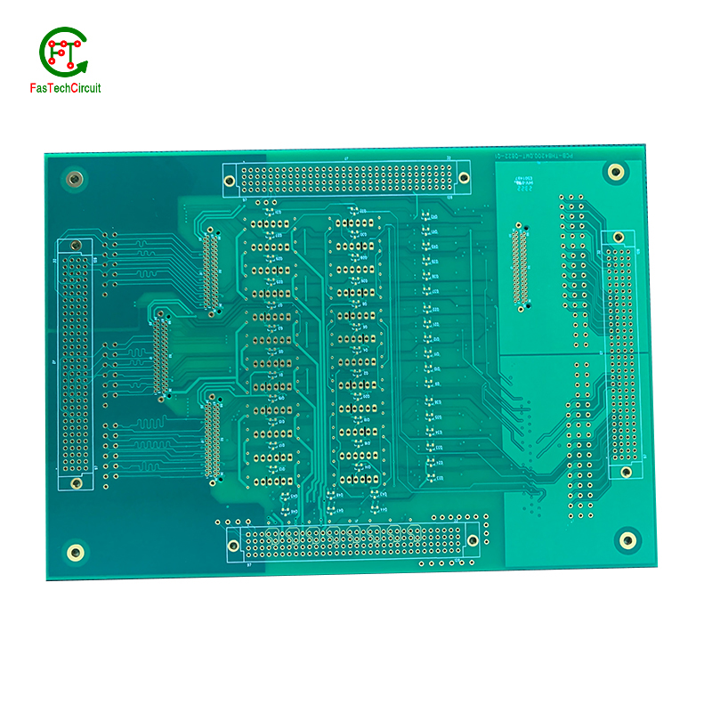
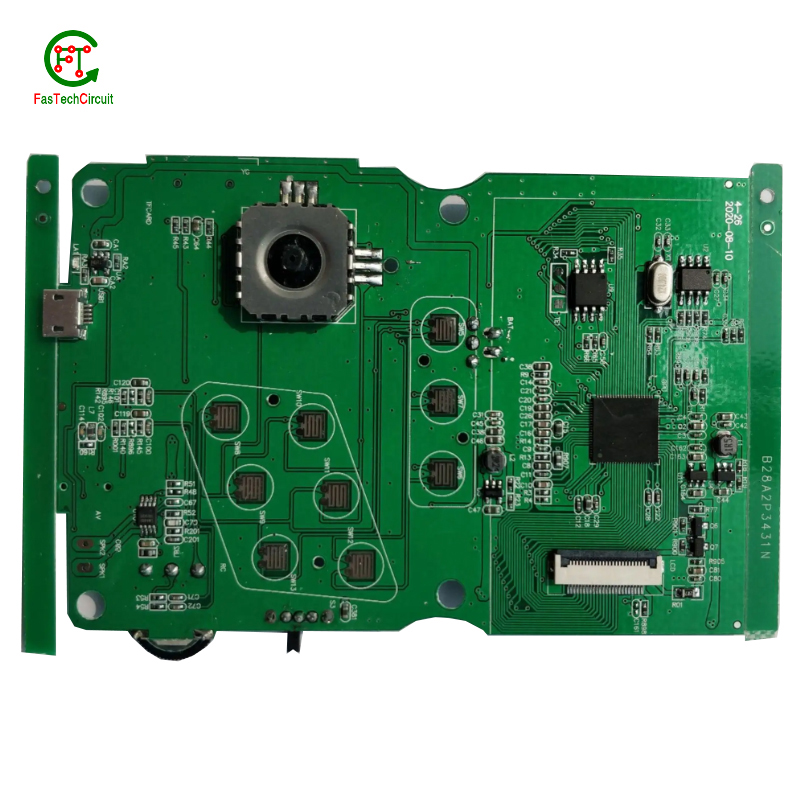
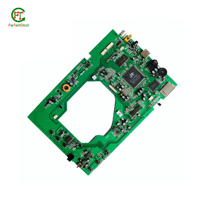
acid trap pcb layout bearings FAQs Guide Welcome to our state-of-the-art PCB (Printed Circuit Board) products. We are proud to offer a comprehensive range of high-quality and versatile PCB solutions to meet the constantly evolving needs of the modern electronics industry.Our PCBs are expertly designed and manufactured using the latest technology and advanced techniques, ensuring reliability, durability, and exceptional performance for a wide range of applications. We understand the importance of precision and attention to detail in the production of PCBs and we are committed to meeting stringent quality standards.
2.What are the advantages of using a acid trap pcb layout?
3.What is the difference between a gold-plated and a tin-plated acid trap pcb layout?
4.How are signal traces routed on a acid trap pcb layout?
5.How are acid trap pcb layouts manufactured?
6.How are signal integrity issues addressed in acid trap pcb layout design?
7.What is the maximum size of a acid trap pcb layout?
8.What is a acid trap pcb layout?
9.What are the benefits of using surface mount technology (SMT) for acid trap pcb layout?
10.What are the main components of a acid trap pcb layout?
11.Can a acid trap pcb layout be used with both through-hole and surface mount components?
12.What is the difference between an analog and a digital signal on a acid trap pcb layout?
13.What are some common problems that can occur with acid trap pcb layout?
14.How are high-speed/high-frequency acid trap pcb layout tested and validated?
15.What does acid trap pcb layout stand for?
1.How are components selected for a acid trap pcb layout design?
We pay attention to employee development and benefits, and provide a good working environment in order to improve the efficiency of employees and improve the quality management of acid trap pcb layout products.
A power rating for a PCB, or Printed Circuit Board, is a measure of the maximum amount of power the board is able to safely handle. This rating takes into account the overall design and materials used in the creation of the PCB, as well as the environment in which it will be used. It is an important consideration in electronics and circuit design as exceeding the power rating can lead to overheating and potential damage to the board and connected components. Properly understanding and adhering to the power rating of a PCB is crucial for ensuring safe and efficient operation of electronic devices.
2.What are the advantages of using a acid trap pcb layout?
We are centered on customers and always pay attention to customers' needs for acid trap pcb layout products.
There are several advantages of using a PCB (Printed Circuit Board). Firstly, a PCB provides a compact and organized layout for electronic components, which makes it easier for technicians to troubleshoot and repair any issues. Secondly, it reduces the chances of loose connections and short circuits, which can be a major safety concern. Thirdly, PCBs are cost-effective and can be easily mass-produced, making them a popular choice for large-scale production. Additionally, they offer durability and stability, ensuring long-lasting performance. Finally, PCBs also allow for easy integration of new components, making it easier to upgrade or modify the electronic devices.
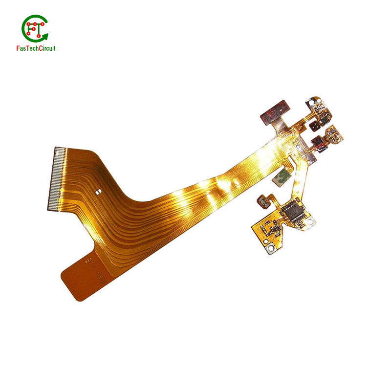
3.What is the difference between a gold-plated and a tin-plated acid trap pcb layout?
A gold-plated PCB (Printed Circuit Board) is a type of PCB that has a thin layer of gold coating on its surface. This layer is added through a process called electroplating and is commonly used to protect the PCB components from corrosion and increase the conductivity. On the other hand, a tin-plated PCB has a layer of tin coating on its surface, which is also applied through electroplating. Unlike gold plating, tin plating is mainly used to prevent oxidization and improve solderability.
4.How are signal traces routed on a acid trap pcb layout?
Signal traces are an essential element of a PCB, responsible for carrying electronic signals between components and ensuring proper communication and functionality of the circuit. To route these traces, designers use specialized software to determine the most efficient and optimal path for each signal, taking into account factors such as signal integrity, trace length, and potential interference. This process involves careful planning, as well as techniques such as vias, ground and power planes, and differential pairs to minimize noise and maintain signal integrity.
5.How are acid trap pcb layouts manufactured?
We have the leading technology and innovation capabilities, and attach importance to employee training and development, and provide promotion opportunities.
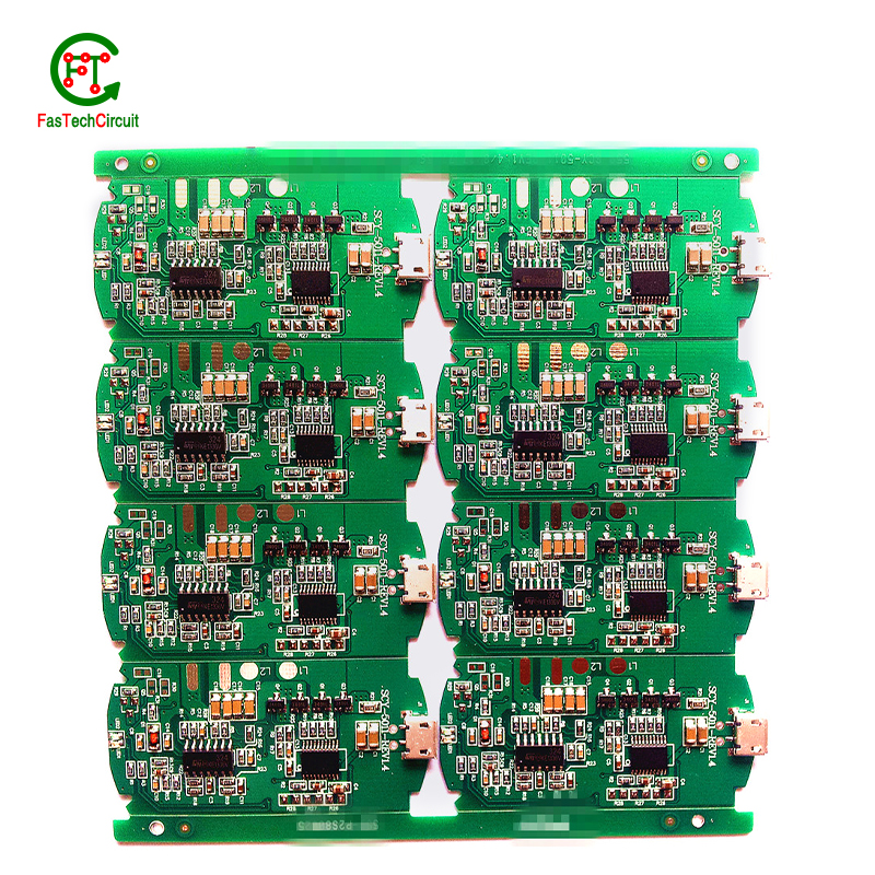
PCB are manufactured through a series of steps starting with designing the circuit layout. Once the design is finalized, the layout is printed on a special type of paper known as the “artwork”. This artwork is then transferred onto a copper-coated laminate board through a process called etching. The excess copper is removed, leaving behind the desired circuit pattern. The board is then drilled to create holes for components to be inserted. The next step involves adding a thin layer of solder mask to protect the circuit and adding a thin layer of copper to create traces. Finally, the components are added using a specialized machine, and the board goes through a series of tests to ensure proper functionality. Once the tests are passed, the board is cut and separated into individual PCBs for use in various electronic devices.
6.How are signal integrity issues addressed in acid trap pcb layout design?
We focus on our customers' needs and strive to meet their expectations, so we take this very seriously.
Signal integrity issues are a common concern in PCB design, as they can greatly affect the performance and reliability of electronic systems. These issues arise from high-speed signal transmissions on the board, which can result in degraded signals, data errors, and even system failures. In order to address these issues, PCB designers must consider various factors such as layout, routing, and component placement to ensure proper signal integrity. This involves implementing signal protection measures such as controlled impedance routing, signal shielding, and minimizing signal crosstalk. Additionally, designers may use simulation and analysis tools to identify and resolve any potential signal integrity problems before the PCB goes into production. By carefully addressing signal integrity issues in the design phase, PCBs can achieve optimal performance and functionality.
7.What is the maximum size of a acid trap pcb layout?
We pay attention to the introduction and training of talents, scientifically regulate the management system, and focus on cultural construction and team cohesion.
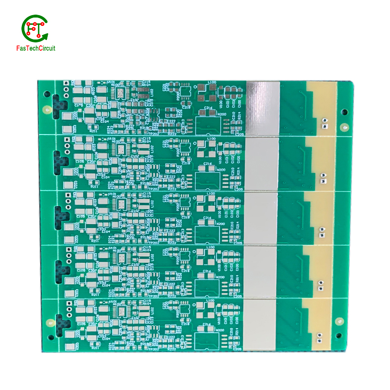
The maximum size of a PCB (printed circuit board) can vary depending on the manufacturer and theircapabilities. However, the industry standard maximum size for a single PCB panel is typically around 18 inches by 24 inches (457 mm by 610 mm). Larger PCBs can be created by combining multiple panels together. Some manufacturers may also have the capability to create custom-sized PCBs that exceed the industry standard maximum size.
8.What is a acid trap pcb layout?
We pay attention to user experience and product quality, and provide the best product quality and lowest production cost for cooperative customers.
A PCB (Printed Circuit Board) is a flat board made of non-conductive material, such as fiberglass, with conductive pathways etched or printed onto it. It is used to mechanically support and electrically connect electronic components using conductive tracks, pads, and other features etched from copper sheets laminated onto a non-conductive substrate. PCBs are commonly used in electronic devices such as computers, smartphones, and televisions to provide a platform for the components to be mounted and connected together. They are also used in a variety of other applications, including automotive, aerospace, and medical devices.
9.What are the benefits of using surface mount technology (SMT) for acid trap pcb layout?
We focus on innovation and continuous improvement to maintain a competitive advantage.
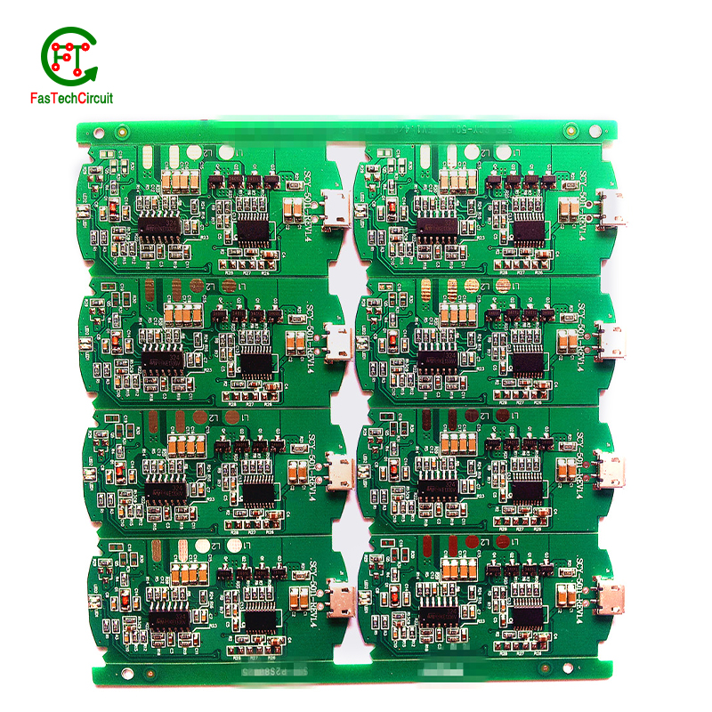
Surface mount technology (SMT) is a popular method for assembling printed circuit boards (PCBs) that offers numerous benefits over traditional through-hole components. Firstly, SMT components are smaller and more compact, allowing for greater PCB density and reducing the overall size of the board. This makes SMT ideal for increasingly miniaturized electronics, such as smartphones and wearables. Additionally, SMT components are typically cheaper and easier to manufacture, leading to cost savings in both materials and labor. SMT also allows for automated assembly, resulting in faster and more efficient production processes. Furthermore, the smaller size of SMT components leads to improved electrical performance due to decreased parasitic effects and shorter signal paths. This makes SMT ideal for high-frequency applications.
10.What are the main components of a acid trap pcb layout?
We continuously upgrade our skills and knowledge to adapt to changing acid trap pcb layout market needs.
A typical PCB consists of several vital components, including a substrate material, copper traces, solder mask, silk screen, and plated through-holes. The substrate material acts as the base and provides mechanical support for the board. Copper traces, usually made of thin lines of copper foil, serve as the conductive paths for transmitting electrical signals. The solder mask, applied as a protective layer, prevents accidental short circuits and corrosion. Silk screen, a layer of ink-based labeling, aids in component identification. Lastly, plated through-holes enable electrical connection between different layers of the PCB board. These components work together to form a fully functioning PCB.
11.Can a acid trap pcb layout be used with both through-hole and surface mount components?
We continue to improve acid trap pcb layout products and processes to improve efficiency.
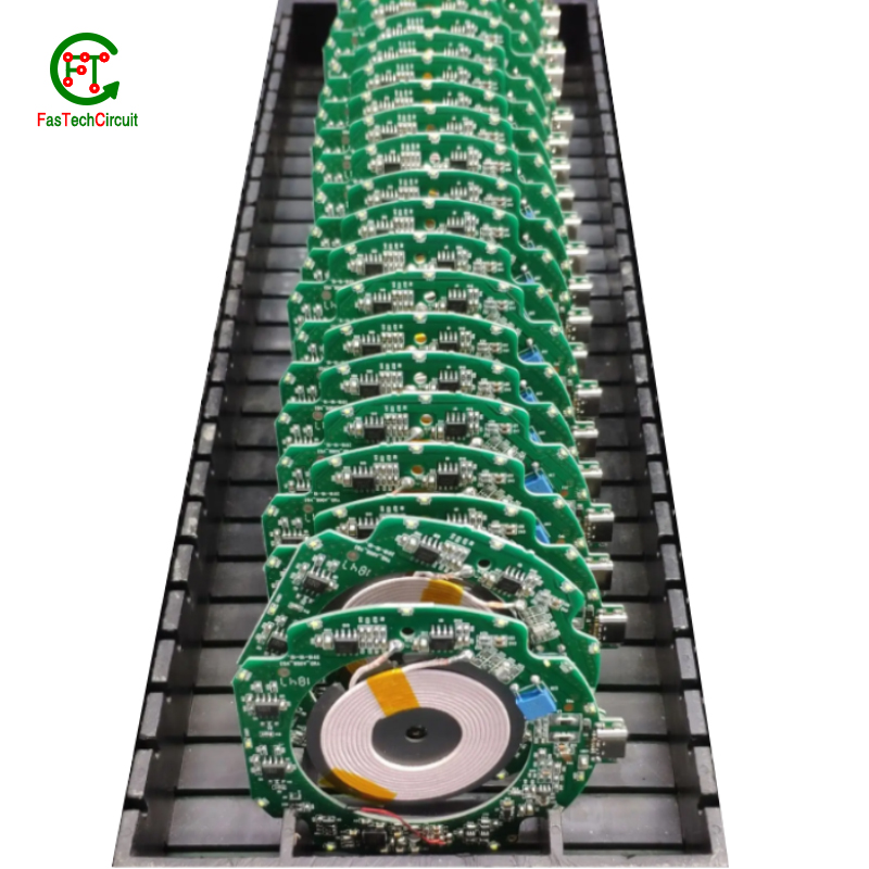
Yes, a PCB (printed circuit board) can be designed to accommodate both through-hole and surface mount components. This is known as a mixed-technology PCB. The PCB will have both through-hole and surface mount pads and traces, allowing for the placement and soldering of both types of components. This type of PCB is commonly used in electronic devices that require a combination of through-hole and surface mount components for functionality.
12.What is the difference between an analog and a digital signal on a acid trap pcb layout?
An analog signal is a continuous signal that varies in amplitude and frequency over time. It can take on any value within a given range and is typically represented by a smooth, continuous waveform. Analog signals are used to transmit information such as audio, video, and sensor data.
A digital signal, on the other hand, is a discrete signal that can only take on a limited number of values. It is represented by a series of binary digits (0s and 1s) and can only have two states: on or off. Digital signals are used to transmit information in the form of data and are commonly used in digital electronics such as computers and smartphones.
On a PCB, the main difference between analog and digital signals lies in the way they are processed and transmitted. Analog signals require specialized components such as amplifiers and filters to maintain their integrity, while digital signals can be processed and transmitted using digital logic circuits. Additionally, analog signals are more susceptible to noise and interference, while digital signals are more immune to these factors.

13.What are some common problems that can occur with acid trap pcb layout?
Our acid trap pcb layout products undergo strict quality control to ensure customer satisfaction.
PCB (printed circuit boards) are an integral part of electronic devices, serving as the foundation for electrical connections and components. However, like any other technology, there are certain issues that may arise with PCB. One common problem is damage to the board due to excessive heat, as electronic components generate heat and if the PCB is not properly designed or ventilated, it can lead to malfunctions or even permanent damage. Another issue is poor soldering, which can result in weak connections or no connection at all. This can be caused by inadequate equipment or inexperience in the assembly process. Additionally, PCB can also suffer from corrosion over time, especially in high humidity environments, affecting its performance and reliability. It is important to address these problems early on to prevent further damage and ensure the functionality of electronic devices. Regular maintenance, proper design and assembly techniques, and use of quality materials can help prevent these common issues with PCB.
14.How are high-speed/high-frequency acid trap pcb layout tested and validated?
Testing and validation are essential steps in the production process of high-speed and high-frequency printed circuit boards (PCBs). These specialized types of PCBs are used in a wide range of industries, including telecommunications, aerospace, and automotive, and require precision and reliability in their performance.
The testing and validation process for high-speed/high-frequency PCBs involves several steps to ensure that the final product meets the required specifications. This starts with design simulation and analysis using specialized software to verify the layout and electrical characteristics of the PCB.
Once the design is confirmed, prototype PCBs are manufactured and subjected to various tests, including signal integrity and power integrity tests. These tests evaluate the electrical performance of the PCB, such as its ability to transmit signals at high speeds and maintain signal integrity.
In addition to electrical tests, environmental and mechanical tests are also performed to assess the durability and reliability of the PCB under different conditions, such as temperature changes and mechanical stress.
The final step in the testing and validation process is the inspection and analysis of the tested PCBs. This involves a detailed review of the test results and any necessary modifications to meet the required specifications.
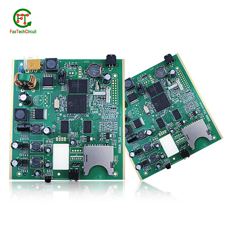
15.What does acid trap pcb layout stand for?
We attach importance to the innovation ability and team spirit of employees, have advanced R & D facilities and laboratories, and have a good quality management system.
PCB stands for Printed Circuit Board.
RELATED PRODUCTS & SERVICE
pcb board manufacturing How To Contact US
PCB from 1 to 30 layers, HDI, Heavy Copper, Rigid-flex board with "pcb board manufacturing One-Stop" service.

